Rj45 Patch Panel Wiring Diagram

Network Patch Panel Wiring Diagram Diagram Base Website Wiring

Kw 5863 Panel Besides 48 Port Patch Panel Rj45 On 48 Port Patch
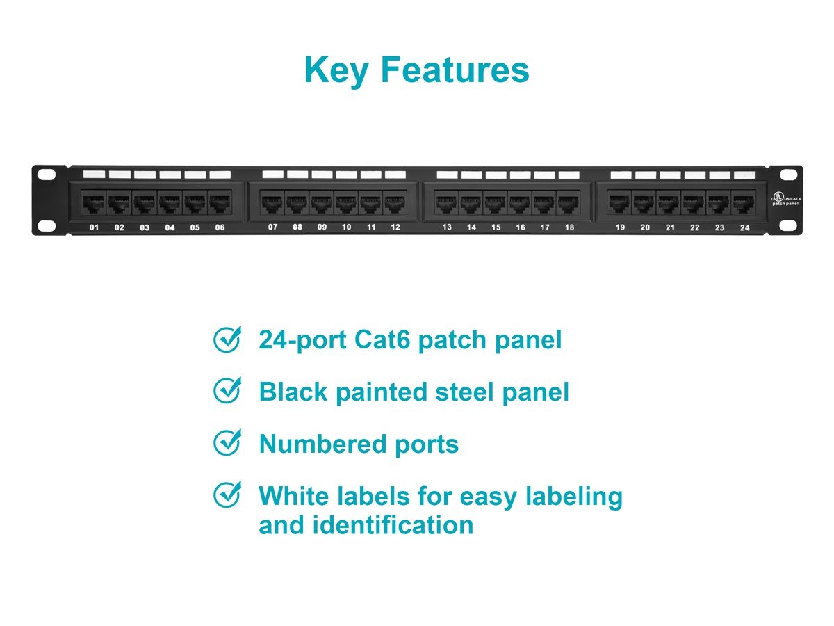
Monoprice 24 Port Cat6 Patch Panel 110 Type 568a B Compatible
However the other end was punched down into a patch panel where the left to right sequence of wires doesnt tell you whether its a or b.

Rj45 patch panel wiring diagram. Cross over pinout a crossover cable utilizes two different rj45 pinouts for the two ends of. So when wiring the cat5e patch panel a big issue is the design and quality of the terminations of cat5e patch cables. Click to check the right one for you or print as reference. The t 568b standard is the most commonly used.
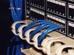
The rj45 jack is an 8 conductor compact modular jack used to terminate utp data cable. How to punch down a network ethernet patch panel. Patch panels have their own custom wiring sequences to maximize ease of installation. We look at the 568a and 568b color codes what they mean and why theyre important.
Terminating cat6 shielded cable with a standard rj45 connector. Rj45 jacks are engineered to maintain specific category 5 5e 6 or 6a performance and therefore must match the category of the cable they are terminating. How to make cat6 patch cord monoprice. The opposite end of the break out cable were going to strip down a sufficient amount of the sheath to separate each colored pair and have a long enough length for each pair to lead it to the various ports.
The wall jack may be wired in a different sequence because the wires may be crossed inside the jack. The complete ethernet pinout cable wiring reference with wiring step by step guide. The first end of the patch cable that plugs into the wall plate patch panel will just be a regular rj45 connector wired the same way that you punched down the cables either t568a or t568b. This video lecture explains the pins and wiring in ethernet cables and rj45 plugs.
The cat5e patch cable is the basic component to connect end devices to patch panel ports and to connect the ports between two local patch panels. The wiring diagram is shown with the hook clip on the underside. Click to find view print and more. The first is the t568a wiring standard and the second is t568b.
If you are unsure of which to use choose 568b. When choosing a suitable patch cable booted and non booted is two basic types of plug features. A patch panel is a series of rj45 jacks condensed onto a single panel. Remember the rj45 wiring order.
T568b has surpassed 568a and is seen as the default wiring scheme for twisted pair structured cabling. Yes one side is a rj45 connector so looking at the colour sequence tells you if that was t 568a or b. We also discuss when and why to use a straight through ethernet patch cable color versus an ethernet crossover cable wiring color code.

Add Support For Tracking Physical Cable Plants Issue 20
Uncle Ted S Guide To Communications Cabling Termination
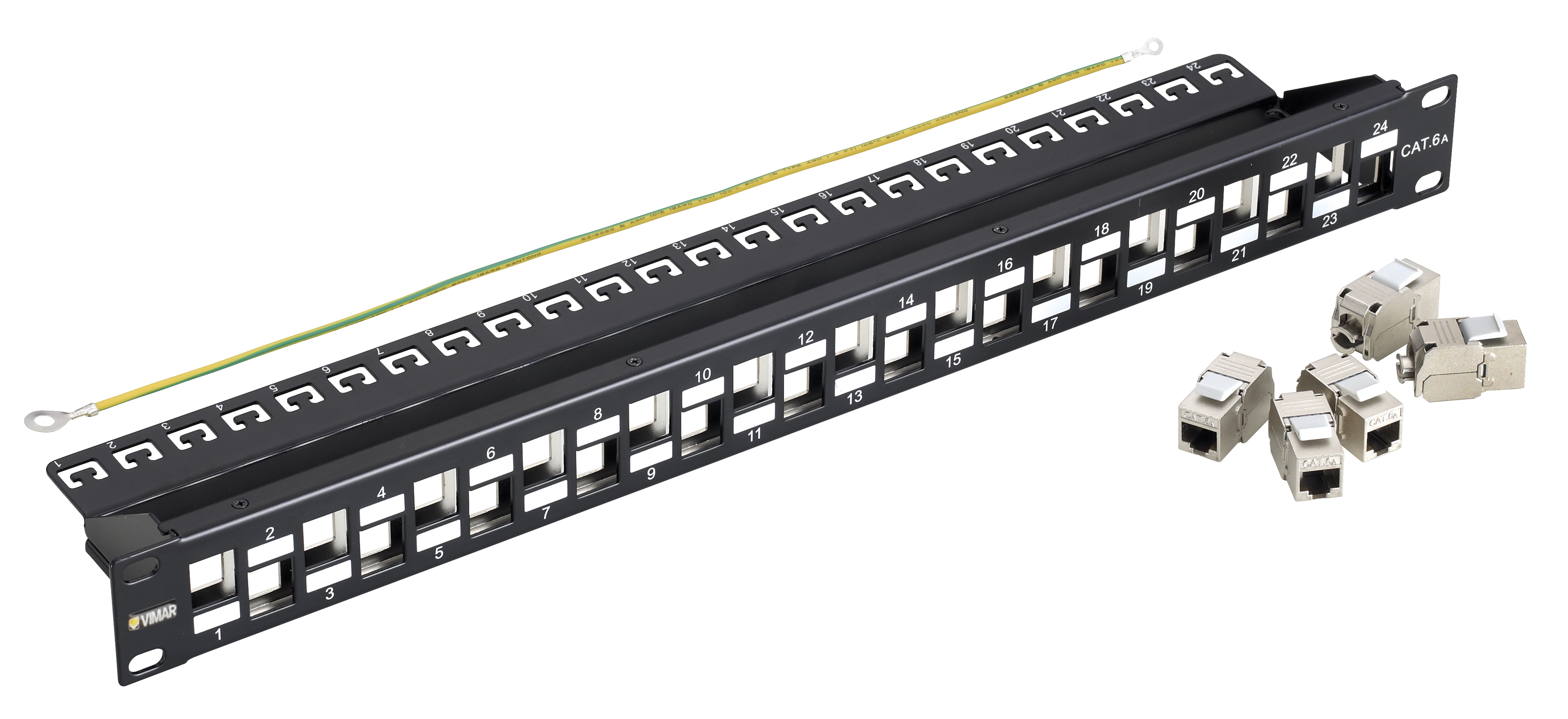
569c Cat6a Patch Panel Wiring Diagrams Wiring Library
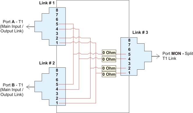
T1 100 Ohms Splitter Patch Panel

Install Patch Panels
Cat5e Rack Wiring Diagram E23 Wiring Diagram

Phone And Computer Connection Diagrams Voip Business Support

Home Office Module 4 4 Patch Panel 1 2 Cable Tv Splitter Module
Network Patch Panel Wiring Diagram
