Same Circuit Light Switch To Outlet Wiring Diagram
Multiple light wiring diagram.

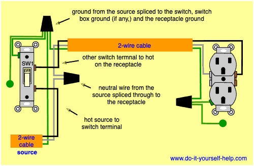
Same circuit light switch to outlet wiring diagram. Namely im trying to put a 240v outlet with no neutral pathway on the same circuit as a lightswitch if possible. It depends how you want the switch and receptacle to function. The source is at sw1 and 2 wire cable runs from there to the fixtures. Wiring a gfci outlet with combo switch outlet receptacle light switch.
This wiring allows the electricity to continue from the receptacle on to any other outlets in the circuit and it provides a switch for controlling a light fixture or other load such as. On the other hand if you simply w. Another nm cable connects the first outlet box to the next boxes and so on until you reach the end of the chain. It means all the connected loads to the load terminals of gfci are protected.
Ive drafted up the following incomplete wiring diagram for reference. Wiring an outlet and a light switch mid circuit. The hot and neutral terminals on each fixture are spliced with a pigtail to the circuit wires which then continue on to the next light. This diagram illustrates wiring for one switch to control 2 or more lights.
This diagram illustrates a switch and receptacle in the same outlet box located in the middle of the circuit. At the outlet location that will feed the new switchlight fixture segment of the circuit remove the outlet cover plate then carefully pull the outlet receptacle out of the box leaving the wire connections intact. In the example there are wire connections made to two screws one brass hot screw and one silver colored neutral screw. If you want the receptacle to be powered all the time and want to use the switch to control a load other than the receptacle you wire it like this.