Scada Wiring Diagram
Single Line Electrical Diagrams Electric Power Measurement And

Plc Scada Programming And Systems Integration Phc General

Ignition Scada Inductive Automation Computer Software Diagram Png
When the io signal wires cannot be separated from the power wiring use shielded multi core cable earthed at the plc end.

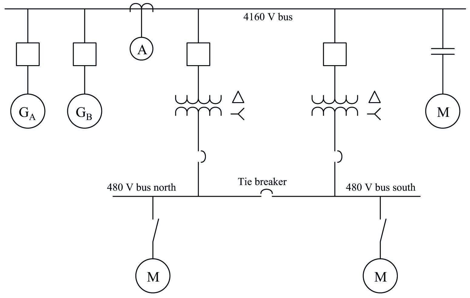
Scada wiring diagram. Electrical cad and wiring diagram software. Components of scada or block diagram of scada. The above figure shows the typical scada based substation control system. The signal cable is numbered with the transmitter number and the wires inside are numbered to provide power source information.
Scada systems was founded in 1985 as a control and data acquisition engineering consultancy. The major components of scada include. Single line diagrams sld a single line diagram shows the disposition of equipment in a substation or network in a simplified manner using internationally accepted symbols to represent various items of equipment such as transformers circuit breakers and disconnectors generally with a single line being used to represent three phase connections. The 420 ma current signal is sourced from the terminal of the transmitter to the plc.
Source of voltage for input to plc applies source of voltage dc 24 volt. Example of wiring diagram plc following way tacking on the cable. How to write a plc ladder logic program. Rtus collect io data and transfers to remote master unit via network interface modules.
About scada systems and the elecdes design suite. Io signal wires should be kept at least 100 mm away from high voltage and large current power circuit wiring. Electrical schematic diagrams wiring diagrams 1 line diagrams cable block diagrams and loop diagrams. Elecdes is the 2d electrical cad design module of eds used for the production of intelligent circuit diagrams including.
To know more about. Various inputoutput io modules connected to the substation equipment gathers the field parameters data including status of switches circuit breakers transformers capacitors and batteries voltage and current magnitudes etc. The transmitter is fed 24 vdc at its positive terminal. Plc scada hmi mmi electrical wiring services electronic wiring services turnkey projects plc scada hmi mmi alarm systems instrumentation mass control wiring systems wiring diagrams studying cable schedules studying services industrial laying as per diagram industrial termination pune maharashtra india.
Difference between dcs plc and scada. Example of wiring diagram for part of input plc input plc applied is limit switch and proximity swtich while plc applied by plc keyence. After identifying the need for automated electrical design software scada systems set about establishing the worlds leading suite of instrumentation panel and electrical cad design software.

Plc Scada Training Public Group Facebook
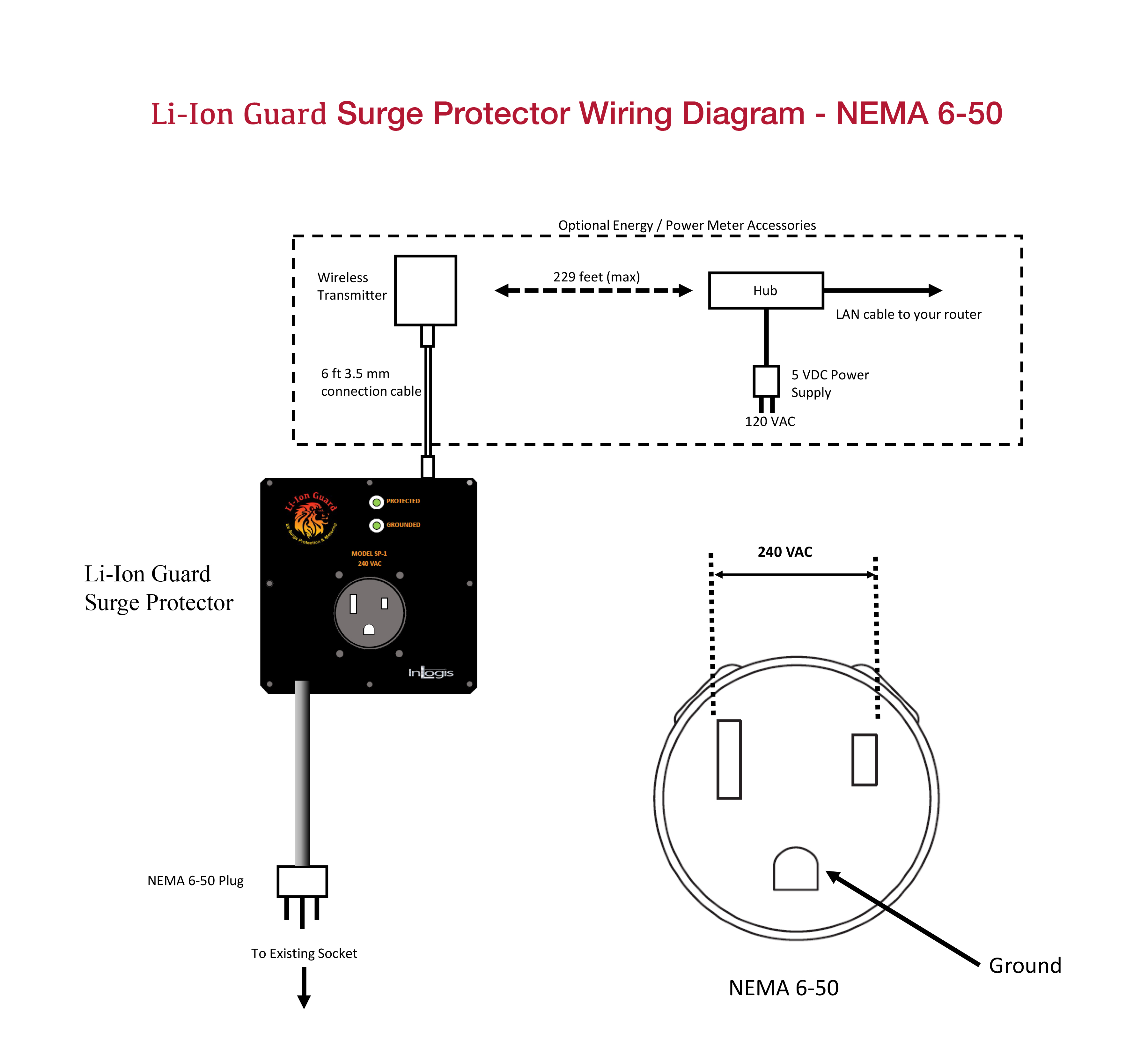
63ba13 Nema 6 50 Plug Wiring Diagram Wiring Library
Five Terms You Must Be Familiar With Scada Dcs Plc Rtu And
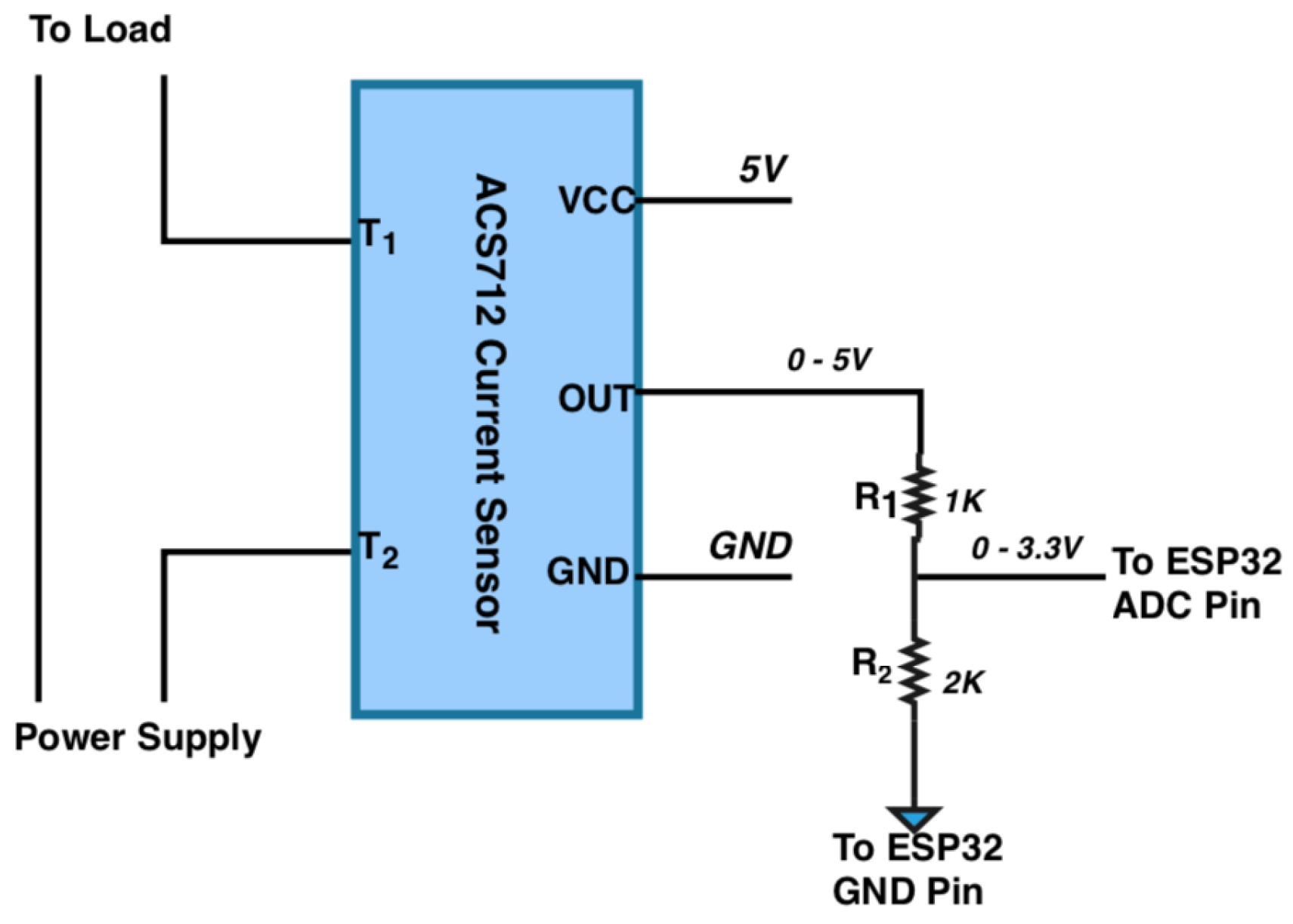
Electronics Free Full Text Low Cost Open Source Iot Based

Figure 5 From Supervisory Control And Data Acquisition System

Scada Wikipedia

Motor Control Circuits Types Electrical Industrial
Process Conrol Process Diagram Component Vc Source Code Hmi
Dnp3 Logo
