Schematic Battery Ignition System Diagram
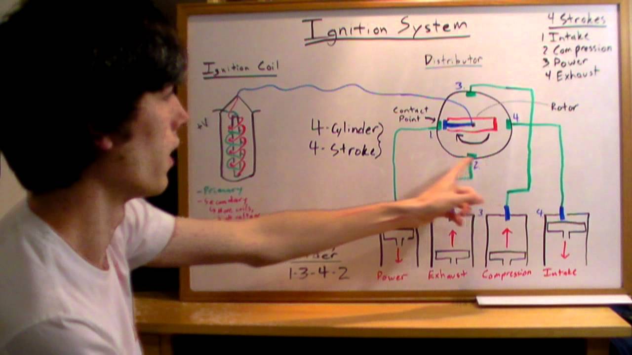
Ignition Systems Explained Youtube
Conventional Ignition Systems Automobile
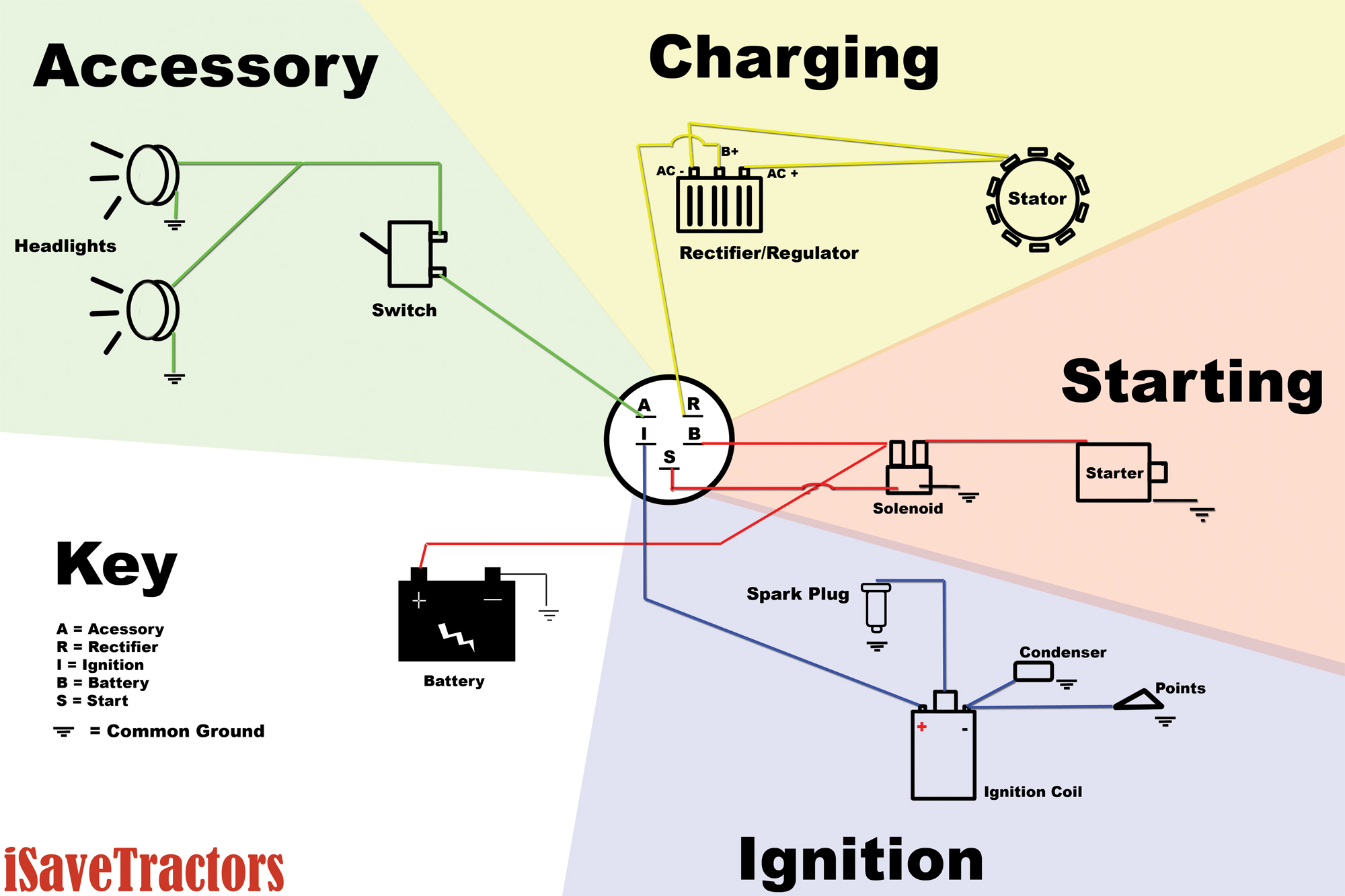
Basic Wiring Diagram For All Garden Tractors Using A Stator And
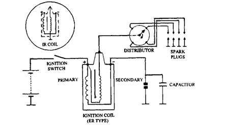
Schematic diagram of ignition system.

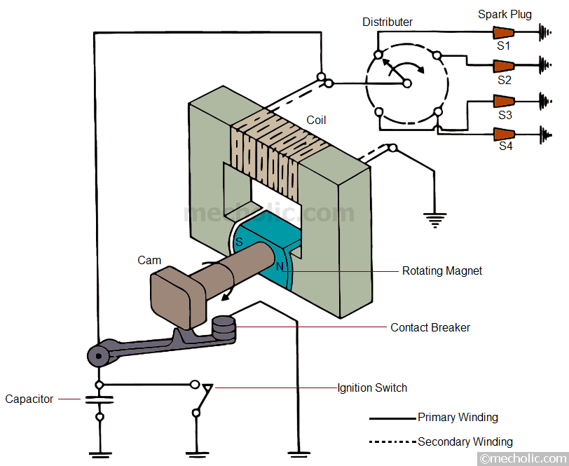
Schematic battery ignition system diagram. One end of the ignition switch is connected to the battery and the other with the primary winding through a ballast resistor. Put up through tops stars team in october 8 2014. See the following schematic representation the battery ignition system circuit for the four stroke engine. A wiring diagram is a streamlined conventional pictorial representation of an electric circuit.
This photograph notes on battery ignition system in schematic diagram of ignition system above can be labelled together with. To discover just about all photos inside schematic diagram of ignition system photographs gallery please comply with go to. Construction of electronic ignition system. Schematic diagram of battery ignition system when the ignition switch and the breaker points are closed a low voltage current flows from the battery through the primary circuit and builts up a magnetic field around the soft iron core of the ignition coil.
With the ignition switch turned on primary battery current flows from the battery through the ignition switch to the coil primary windings. It is a switch that is used to on or off ignition system. The ignition coil is the source for the ignition energy in the battery ignition system. It will deliver the ignition energy in the form of a surge of the high voltage current to the spark plug.
It shows the components of the circuit as simplified shapes as well as the power as well as signal connections between the devices. In addition the section of the primary circuit from the battery to the battery terminal at the coil is the same as in a conventional ignition system. It consists of a battery ignition switch electronic control unit magnetic pick up reluctor or armature ignition coil distributor and spark plugs. An ignition system generates a spark or heats an electrode to a high temperature to ignite a fuel air mixture in spark ignition internal combustion engines oil fired and gas fired boilers rocket engines etcthe widest application for spark ignition internal combustion engines is in petrol gasoline road vehicles such as cars and motorcycles.
A schematic diagram of an electronic ignition system is shown in figure 236.


Cdi Capacitor Discharge Ignition Circuit Demo Ignition Coil

Schematic Diagram Of The Multi Sensing Fuel Injector Msfi

Capacitor Discharge Ignition System Cdi System Youtube

How Battery Ignition System Works Automobile Engineering Youtube
Kia Sportage Starter Schematic Diagrams Starting System
Magneto Ignition System Construction Working Applications

How Does The Car Charging System Work Youtube

Motorcycle Charging System Wiring Diagram 12v Wiring Schematic
