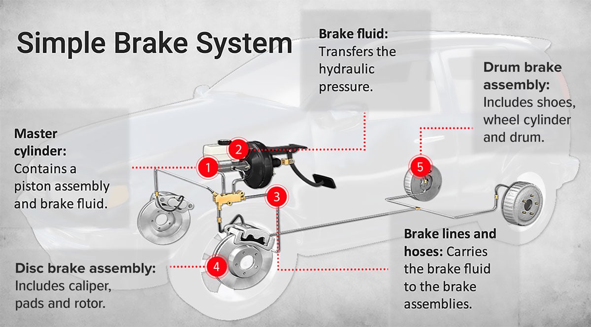
Schematic Disc Brake Line Diagram
This diagram shows a typical street rod brake system.

Schematic disc brake line diagram. On this particular brake system fabrication a bulk stainless brake line and fitting kit sourced from speedway motors was chosen over the use of multiple lengths of auto parts store brake line. Disc brake diagram this disc brake diagram outlines how disc brakes work. Brake system diagram tapered wear a gradual slope of the pad material creating uneven thickness on either end of the pad. Please make sure you get the right details for your car as i cantwont be held responsible for any errors on a critical part of the.
When using a dual master cylinder with disc front drum rear combinations you wont need to remove the residual check valve as it only applies pressure to the rear brake line. Various brake diagrams i used for reference. Now lets put the parts together to see how disc brakes work as a whole. Has me scratching my head but i do love a challenge.
I have been asked if there were any diagrams that i used so here are a few of the more useful ones. Starting from scratch and building custom brake and fuel lines. A 2 psi residual pressure valve rpv is needed in the disc brake circuit and a 10 psi rpv is required in the drum brake circuit as well as an adjustable proportioning valve apv. This diagram shows the basic parts that make up a disc brake system.