Schematic Symbols Electronics
Well go over all of the fundamental schematic symbols.

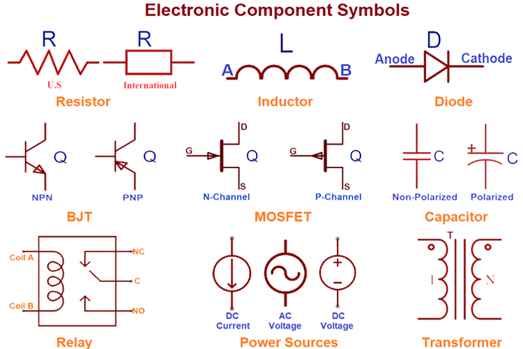
Schematic symbols electronics. These are mostly we used for draw circuit diagrams. Electrical symbols electronic symbols. There are some standard symbols to represent the components in a circuits. Understanding how to read and follow schematics is an important skill for any electronics engineer.
Circuit symbols are used in circuit diagrams which show how a circuit is connected together. The symbols listed in this handbook were collected after much research by the technical staff of cleveland institute of electronics inc. To be able to read schematics you must know the schematic symbols. There are hundreds of different types of electronic components and each has its own unique schematic diagram symbol.
If a part doesnt have a symbol or footprint when clicking on the icon to download you can build one or request a part. The symbols represent electrical and electronic components. They are mostly used to draw a circuit diagram and are standardized internationally by the ieee standard ieee std 315 and the british standard bs 3939. Schematics are our map to designing building and troubleshooting circuits.
Once selected the schematic symbols pcb footprints and 3d models are immediately available for use and placement. Most electronic circuits will have additional components. Fortunately you need to know only a few basic symbols and labels to get you started. There are many electrical and electronic schematic symbols are used to signify basic electronic or electrical device.
This article gives some of the frequently used symbols for drawing the circuits. A large and a small line is suppose to represent one battery cell so that the image below would suggest a two cell battery of 3 v. Note that when used. Here is an overview of the most used symbols in circuit diagrams.
In electronic circuits there are many electronic symbols that are used to represent or identify a basic electronic or electrical device. An electronic symbol is a pictogram used to represent various electrical and electronic devices or functions such as wires batteries resistors and transistors in a schematic diagram of an electrical or electronic circuitthese symbols are largely standardized internationally today but may vary from country to country or engineering discipline based on traditional conventions. To build simply use the wizard from samacsys to create both the schematic symbol and pcb footprint. Because the electronics industry has not adopted a single symbology standard cie has included the most frequently used symbols that represent each component.
This tutorial should turn you into a fully literate schematic reader. The index lists components by general classification. Electrical symbols and electronic circuit symbols are used for drawing schematic diagram.