Schematic Symbols Of Electronic Components And Their Functions
This article gives some of the frequently used symbols for drawing the circuits.
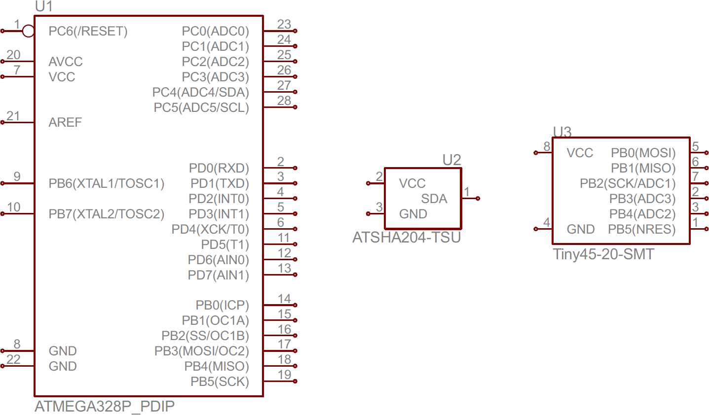
Schematic symbols of electronic components and their functions. This article gives an overview of electronic circuit symbols with their functionality. These are mostly we used for draw circuit diagrams. If you want to focus on core side projects like electronics electrical you should know the basic concepts of electronic circuit symbols and their usage. An electronic symbol is a pictogram used to represent various electrical and electronic devices or functions such as wires batteries resistors and transistors in a schematic diagram of an electrical or electronic circuitthese symbols are largely standardized internationally today but may vary from country to country or engineering discipline based on traditional conventions.
Integrated circuit an. Watch this video for electronic components and their symbols and also get idea on how to different electronic components in circuits http. There are many electrical and electronic schematic symbols are used to signify basic electronic or electrical device. Share on tumblr the symbols are very important to represent electronic components in a circuit diagram without electronic symbol the design of circuit and schematics are very difficult and also knowing the components is very must to read the circuit diagram representation.
Circuit symbols are used in circuit diagrams which show how a circuit is connected together. These terms are often used interchangeably and if you arent familiar with working in schematics you can get lost trying to figure it out. In this tutorial were going to give you a brief overview of common electronic components and explain what their functions are. The symbols represent electrical and electronic components.
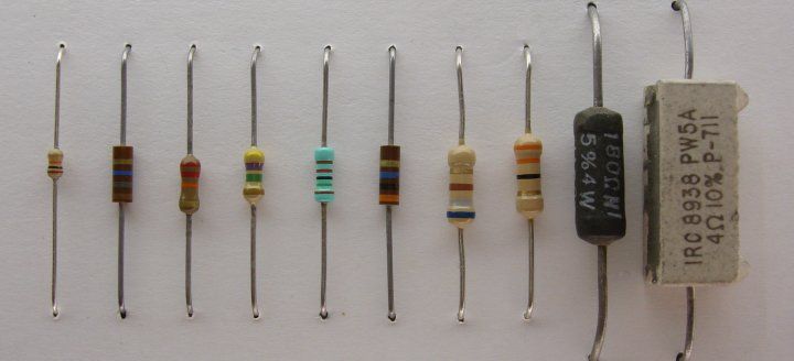
Identifying electronic components and circuit symbols if there is one schematic concept that can cause a lot of confusion it is understanding the difference between a component and a symbol. Computer thinks and functions. There are some standard symbols to represent the components in a circuits. Electrical symbols electronic symbols.
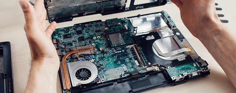
The actual layout of the components is usually quite different from the circuit diagram. Schematic symbols bjt pnp bjt npn p channel fet n channel fet 17. The electronic components are soldered on circuit boards to make a system. Electrical symbols and electronic circuit symbols are used for drawing schematic diagram.
Symbols even more the electronic components have terminals and each will have its own name and polarities.


