Series Circuit Diagram With Ammeter And Voltmeter
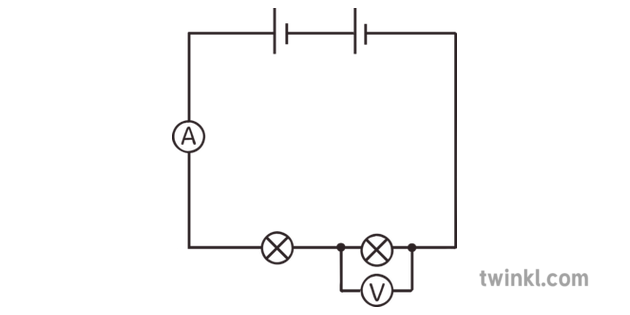
Circuit Voltmeter Ammeter Black And White Illustration Twinkl
How Is The Voltmeter And Ammeter Connected In A Circuit Quora

Series Circuits Series And Parallel Circuits Siyavula
I guess if you connect your voltmeter wrong youll just get bad readings.
Series circuit diagram with ammeter and voltmeter. This is a common question to so many students. Difference between ammeter voltmeter the major difference between the ammeter and the voltmeter is that the ammeter measures the flow of current whereas the voltmeter measures the emf or voltage across any two points of the electrical circuit. Voltmeter ammeter description this voltmeter ammeter was designed to measure output voltage of 0 70v 0 500v with 100mv resolution and 0 10a or more current with 10ma resolution. Circuit diagram ammeter circuit diagram ammeter voltmeter circuit diagram ammeter symbol wiring diagram ammeter wiring diagram ammeter selector switch.
It is a perfect addition to any diy laboratory power supply battery chargers. Circuit diagram ammeter. The answer is very simple. Series circuit diagram with ammeter and voltmeter series circuit diagram with ammeter simple ammeter circuit diagram circuit diagram of galvanometer to ammeter.
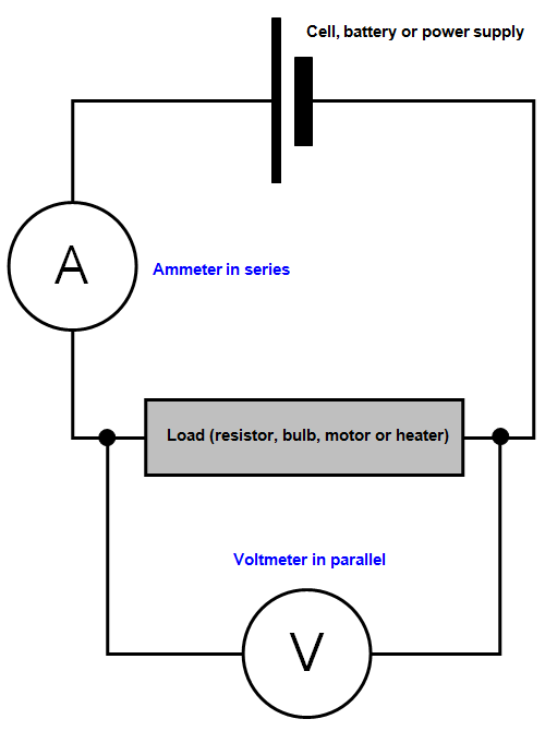
Physicshelp canada 300290 views. Ammeters can be easily damaged. The ammeter is connected in series for the measurement of current and the voltmeter is connected in parallel for the measurement of voltage. All of the current in this circuit flows through the meter.
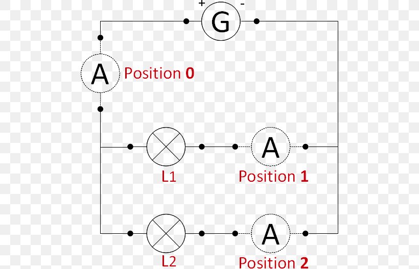
The other differences between the ammeter and voltmeter are presented below in the comparison chart. The ammeter would have the same reading if located between points d and e or between points f and a as it does in the position shown. And stop saying ampmeter it sounds like you. So i want you to determine what other components must be connected to the meter movement to limit the current through its coil so that connecting the circuit in series with a 1 amp circuit results in the meters needle moving exactly to the full scale position.
Connect your circuit components carefully. Series and parallel circuits electricity diagrams part 4 duration. Drawing electric circuits with volt meters. First you have to know there basics of an ammeter and voltmeter.
Note that 5 v applied to this voltmeter produces a half scale deflection by producing a 2. The voltmeter is a measuring device by which we can measure electrical pressure or. An ammeter is used to measure the current passing through it which means the current which we want to measu. Question 2 we know that connecting a sensitive meter movement directly in series with a high current circuit is a bad thing.
Https Encrypted Tbn0 Gstatic Com Images Q Tbn 3aand9gcrn2rrfsolzhnte Ecip8x1nbexwouhggbun6a6 8fawfbqzv T Usqp Cau

Activity Two Series And Parallel Circuits
Schoolphysics Welcome

Voltmeters And Ammeters Boundless Physics
Series And Parallel Circuits Ammeter Electrical Network Electric

To Draw The Diagram Of A Given Open Circuit Comprising At Least A

Difference Between Ammeter And Voltmeter In Tabular Form

Searching For Patterns In Series And Parallel Circuits

Moving Coil Meters
