Servo Drive Schematic
Servo Motor Control With An Arduino Projects
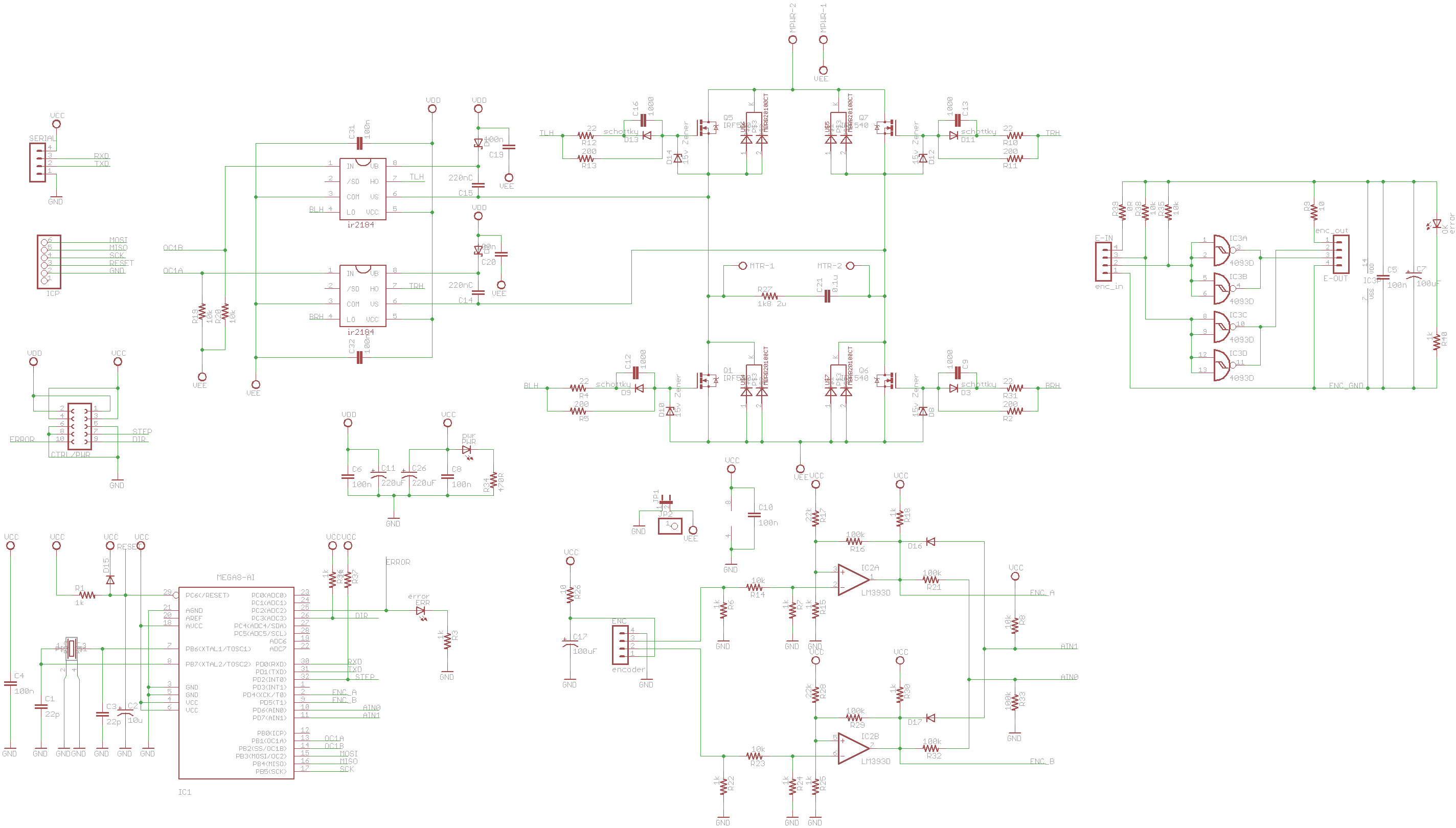
Atmega88 Ir2184 Dc Servo Motor Driver Circuit Electronics
Sik Experiment Guide For Arduino V3 3 Learn Sparkfun Com
At the same time it is also the most easily damaged device by many factors.

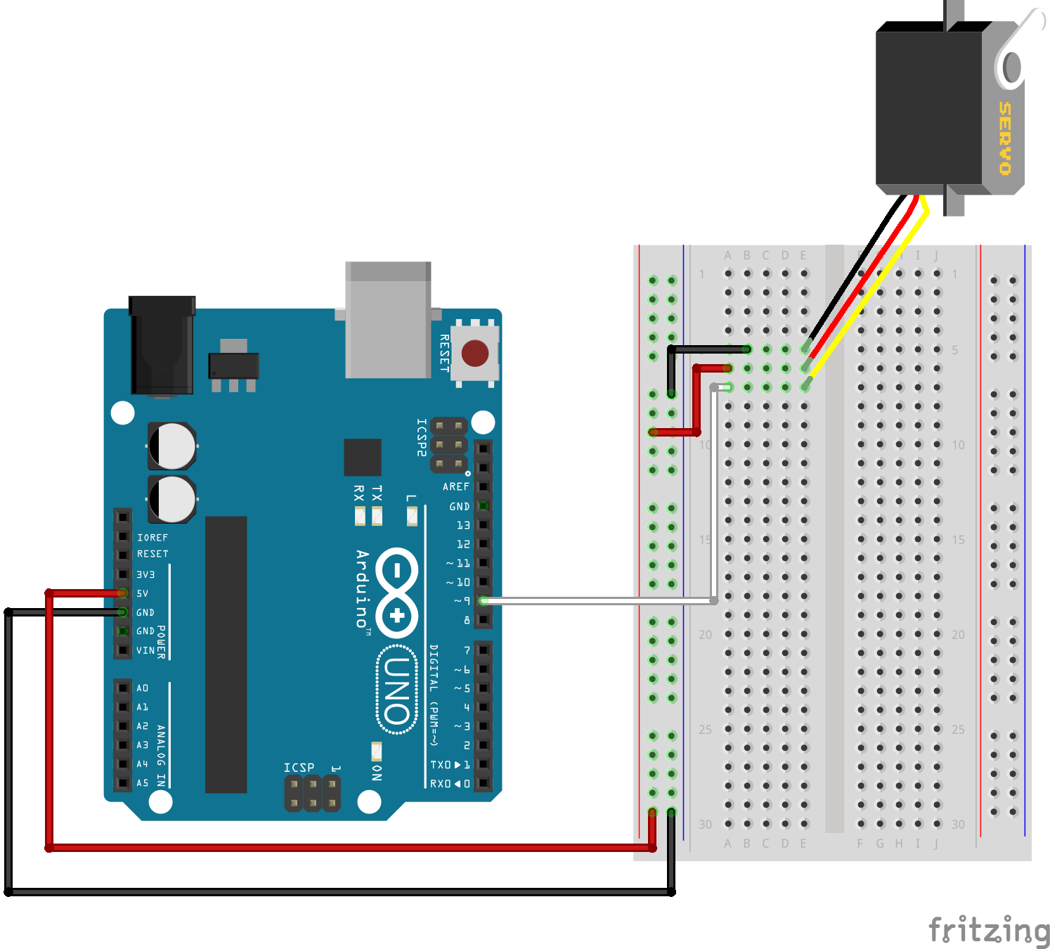
Servo drive schematic. 100200vac input 30w isolated power supply reference design for servo drives. 513 schematic diagrams. The circuit shcematic we will build is shown below. Name part number tool type.
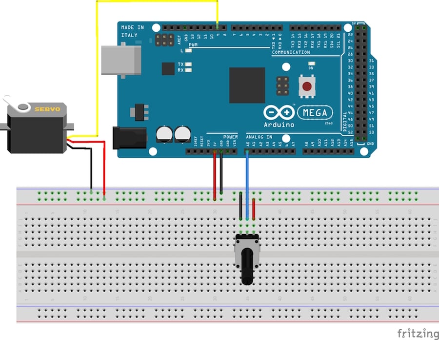
Servo motor is one of the most commonly used equipment in all machines thanks to its advantages. All we need now is the code to make the servo rotate. This servo drive is able to supply a brushed dc motor with up to 7 a continuous current at up to 36 v approximately 250 w or 13 hp while also performing closed loop control with feedback from a quadrature encoder and accepts the widespread stepdir signals. Real time control powerful processing precise analog signal chain and robust transceivers help run fast control algorithms and encoder interfaces.
The servo drive is able to supply a brushed dc motor with up to 7 a continuous current at up to 36 v which works out to about 250 w or 13 hp. If you want to see if a car of your own design will steer properly it would be useful to have a simple circuit that allows you to control the servo and put it through its paces. Thus providing a drop in replacement for the ubiquitous stepper motor in linear positioning applications like those found in you. This is the simple basic design of servo motor controller with pulse generator.
62 drive configuration sequence. Code must include servoh library in order to work. Our integrated circuits and reference designs help you create servo drive control modules for precise smooth and efficient control of servo motors. A servo is a small device that has an output shaft.
Cdhd user manual 3 revision history document. So you can see all connections of the servo made to the arduino board. It uses the cmos ic 7555 in the astable mode to generate pulses to drive the servo motor. Servo motor circuit schematic.
The above picture is a schematic for a circuit that does just that. The price of a servo motor is not cheap especially drive is more expensive and more prone to damage than the motor. Mitsubishi electric fa site introduces information in latest information product information technological material and the manual etc. Reference design 230v 900w pfc with 98 efficiency for inverter fed drives reference design.
The code is shown below. Cdhd servo drive user manual 120240 vac and 400480 vac revision 72 doc cdhd um en.

555 Timer Servo Motor Controller Multisim Live

Servo Motor Controller Circuit
Https Www Jstor Org Stable 24110424

Question About Ac Servo Motor Driver Electrical Engineering
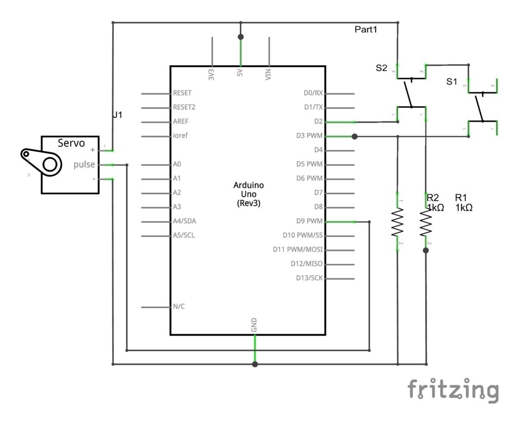
Servo Control By Push Button Switch Arduino

How To Build A Servo Motor Circuit With Arduino
Pololu Advanced Hobby Servo Control Pulse Generation Using
First Servomotor Control Program
Dc Servo Motor Driver Electronics Lab
