Servo Motor Driver Circuit Diagram

Td 2217 Servomotordriveamplifier Amplifiercircuit Circuit Diagram

H Bridge Motor Control For Diy Servo General Discussions

12f675 Tutorial 6 Driving A Servo Motor Using A Pic Micro
Pic16f628a l297 stepper motor driver with l298 schematic circuit diagram high voltage 0 400v 22ma 600ma regulated power supply tca785 schematic circuit diagram tda7560 4x50 watt bridge auto amplifier schematic circuit diagram.

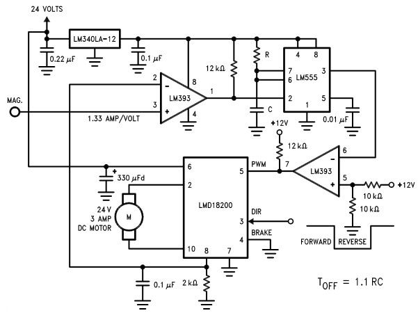
Servo motor driver circuit diagram. Learn how to use a 555 timer chip in order to control the movement of a servo motor. Here sub micro size servo motor is taken as a target device and we developed servo motor driver circuit for that motor. 33kw 10kw 2peices 68kw and 220w resistors. The circuit can be suitably modified to get pulses of sufficient length.
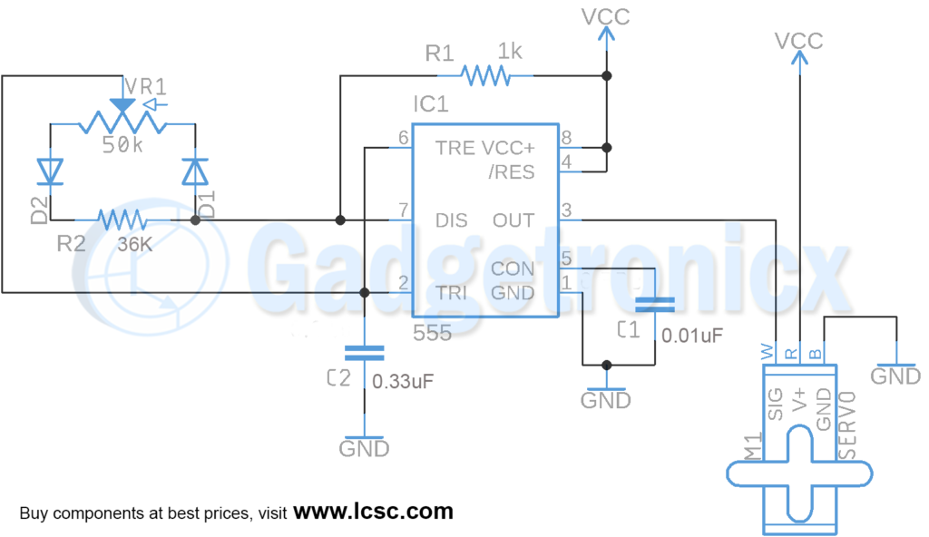
A servo is a small device that has an output shaft. The output of the circuit goes to control input pin in servo motor servo motor ground goes to circuit ground and servo power input goes to suitable power source can be the same 5v as used to power this circuit. This is a 555 timer in astable mode which can generate a frequency with a low duty cycle in order to control a. Servo motor which needed to be tested 555 timer ic.
Easy to build cnc mill stepper motor and driver circuits. This is a follow up to the easy to build desk top 3 axis cnc milling machine once you get the machine all put together its time to make it go. Servo motor basics and controll ciruits diagram pdf. Two buttons servo tester circuit diagram and working explanation.
Motor control circuit diagram also servo block servo motor driver circuit using ic 555 gadgetronicx servo motor controller circuit dc servo motor driver electronics lab whats people lookup in this blog. It uses the cmos ic 7555 in the astable mode to generate pulses to drive the servo motor. The pinouts used on differnet servo motors vary but the wire colors are generally so that black is ground read is power and the. So its time to drive the motors.
Now as we discussed earlier for the servo shaft to move left all the away. A servo testing circuit is shown in the above schematic diagram. And here ive put together a circuit that i think is the absolute che. Dc servo motor driver electronic circuit diagram circuit and wiring diagram download for automotive car motorcycle truck audio radio electronic devices home and house appliances published on 13 jun 2016.

Servo Motor Driver Circuit
Dc Motor Servo Circuit Composed Of Ma741 Basic Circuit Circuit
Results Page 39 About Infra Red Motor Searching Circuits At
Servo Motor Control Using Ic 555 Gadgetronicx
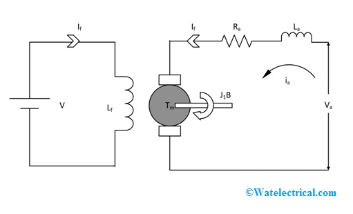
Dc Servo Motor Characteristics And Its Applications
Https Encrypted Tbn0 Gstatic Com Images Q Tbn 3aand9gcqkytkagxwrkuyoiz Bxksg8rayvow6bzl4h3wkhfiijih5nv9u2xdnvmlpa1jjeclcwjtddue Loetako4ilzho59ksulzfdff Usqp Cau

Servo Motor Controller Using 555 Ic Circuit Diagram
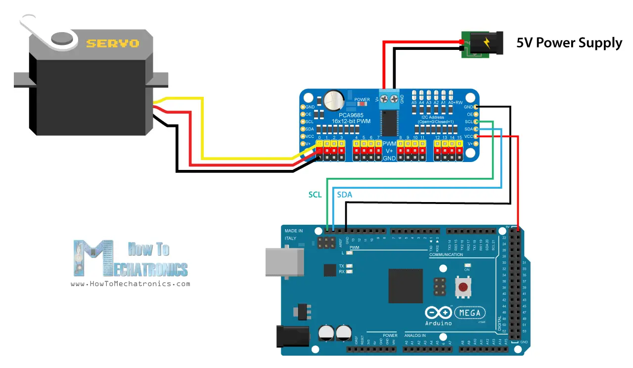
How Servo Motor Works How To Control Servos Using Arduino
Connection Diagram Reference Specifications Of Servo Amplifier
