Servo Voltage Stabilizer Circuit Diagram

Difference Between Relay Stabilizer Servo Stabilizer

China Honle Svc Series Automatic Voltage Stabilizer Circuit

Pdf Design Calculation Of Automatic Voltage Stabilizer Control
Definition working principle diagram applications servo mechanism.

Servo voltage stabilizer circuit diagram. A servo voltage stabilizer is a closed loop control mechanism which serves to maintain balanced 3 or single phase voltage output despite fluctuations at the input owing to unbalanced conditions. For the microcontroller circuit we use an external crystal of 4 mhz. Basically there are two types of stabilizers one is relay based and the other is servo based. But of course it can be very amusing to build one at home all by you and see it actually working.
Automatic voltage stabilizer circuit diagram 2. Automatic voltage stabilizer circuit diagram voltage stabilizer circuit operation. Varsan variac and voltage stabilizer 21821 views. The servo stabilizer has definitely an edge over traditional stabilizers.
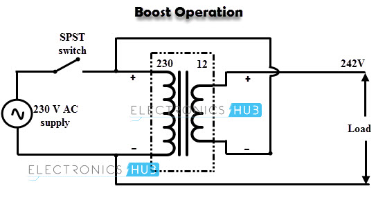
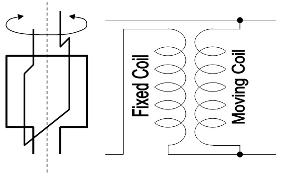
The circuit diagram of a solid state voltage stabiliser is shown in fig2. As soon as it detects any rise or fall in the input supply beyond the reference value it starts operating the motor which further moves the arm on the auto transformer. Buckboost transformer connected between mains input and out of stablizer of load terminals. 11 circuit diagram of servo based voltage stabilizer the electronic circuit board carries out the comparison of the output voltage with the reference voltage source.
A 5v dc input is used to power the microcontroller. There are huge varieties of voltage stabilizers available in the market and surely itx27s not a big deal to procure one according to the needs. The circuit of an automatic voltage stabilizer avs described in this article is in fact very simple in design reasonably precise and will give a. What is a servo motor and how it works.
A wide variety of servo stabilizer circuit diagram options are available to you such as svc. It is used as led type bar graph voltmeter with lower voltage and upper voltage settings through presets vr1 and vr2. Servo motor controlled automatic voltage stabilizer consists of following components please refer servo stabilizer circuit diagram shown below. The heart of the stabiliser is ic1 lm3914 bar display driver.
How servo stabiliser works. In relay stabilizer a switch corrects the output voltage accuracy at 10.
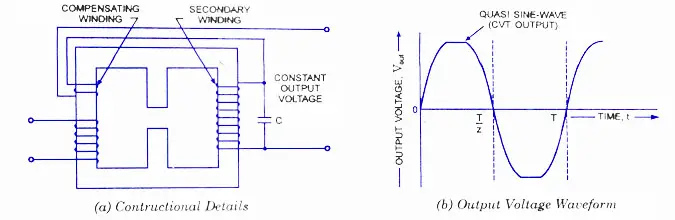
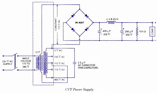
Cvt Constant Voltage Transformer Working Circuit Diagram Application
Voltage Stabilizer Working And Its Importance
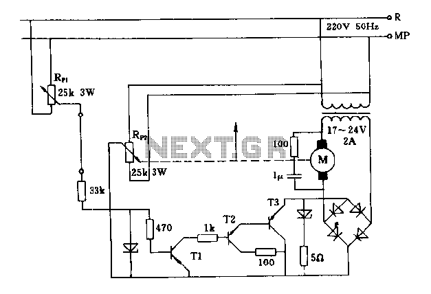
Servo Motor Circuit Automation Circuits Next Gr

Pdf Implementation Of A Microcontroller Based 5 Kva Automatic

Three Phase Voltage Regulator Sirius 60 6000 Kva Three Phase
Different Types Of Voltage Stabilizers To Protect Your Home

Servo Stabilizer

What Is The Difference Between Relay Type Voltage Stabilizer And Ser
Cvt Constant Voltage Transformer Working Circuit Diagram Application
