Si Engine Valve Timing Diagram
Rahul bawane 6402 views.

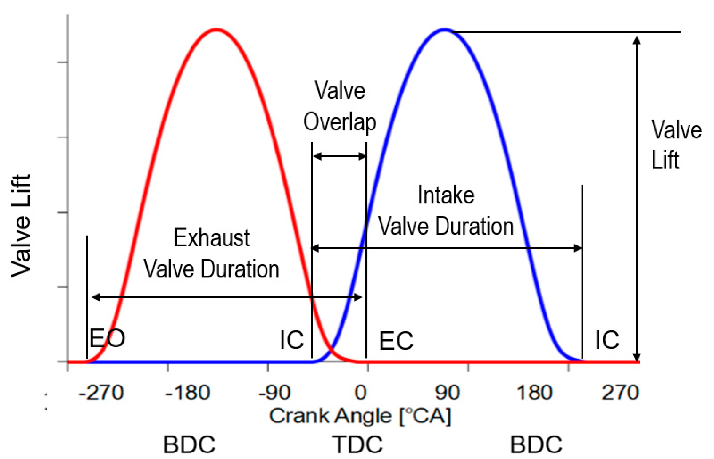
Si engine valve timing diagram. Valve timing diagram of four stroke si engine amit mandal. The diagram which shows the position of crank of four stroke cycle engine at the beginning and at the end of suction compression expansion and exhaust of the engine are called as valve timing diagram. But in actual practice they do not open and close instantaneously at dead centres. Valve timing diagram for two stroke petrol si engine.
In four stroke petrol engine we use the air fuel mixture and spark plug for the combustion process. We have discussed the valve timing diagram for the four stroke diesel engine only. Everything will be the same as this valve timing except the fuel ignition principle. We consider that the valves open and close at the dead centre positions of the piston.
For the four stroke petrol engine also we can draw valve timing. How to draw valve timing diagram 4 stroke si engine duration. Internal combustion engines camshaft. Valve timing diagram four stroke petrol engine.
The valves operate some degrees before or after the dead centres. Valve timing is the regulation put on the engine valves how they set to open and close during working cycle. The diagram shows the timing of opening and closing of intake and exhaust valve during one complete cycle of four strokes. In four stroke cycle engines and some two stroke cycle engines the valve timing is controlled by the camshaftit can be varied by modifying the camshaft or it can be varied during engine operation by variable valve timingit is also affected by the adjustment of the valve mechanism and particularly by the tappet clearance.
Four stroke cycle diesel engine 2. Piece of paper theory and description. How to draw valve timing diagram 4 stroke si engine duration. Engine cycle starts wit.
Valve timing diagram for 2 stroke petrol engine. Port timing diagram for si engine in the valve timing diagram as shown we see that the expansion of the charge after ignition starts as the piston moves from tdc towards bdc.
