Simple Circuit Diagram Resistor
5 8 Building Simple Resistor Circuits Workforce Libretexts
Schematic Diagrams Mastering Arduino

10 3 Resistors In Series And Parallel Physics Libretexts
Share on tumblr if you want to built simple audio amplifier without messy components then you can construct simple single transistor audio amplifier circuit using bc547 and resistor capacitor.

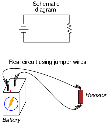
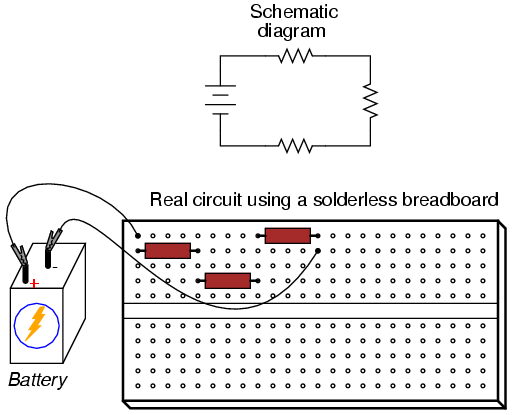
Simple circuit diagram resistor. Progressing from a nice neat schematic diagram to the real circuitespecially when the resistors to be connected are physically arranged in a linear fashion on the terminal stripis not obvious to many so ill outline the. Translating a simple parallel circuit into a circuit layout consider the case of a single battery three resistor parallel circuit constructed on a terminal strip. Resistor 1 220k or 330k or 1k power source battery 9v. An ldr or light dependent resistor is a resistor where the resistance decreases with the strength of the light.
Here is the schematic diagram of this circuit. The circuit diagram for leds in parallel connection is shown in the following image. The circuit diagram present here is that of a street light that. The tuned circuit is high impedance at resonance.
This ldr circuit diagram shows how you can make a light detector. Two types of single transistor audio amplifier circuit designed with bc 547 transistor. By using a table to list all voltages currents and resistance in the circuit it becomes very easy to see which of those quantities can be properly related in any ohms law equation. It can be used to activate any 220 volt ac devices at night and turn off during the daytime.
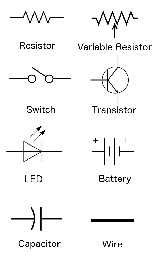
Apply 9 volt dc supply for better result. A circuit diagram is a visual representation of the circuit using meaningful symbols and it gives you an idea of what the connections look like which in turn gives you an idea of how the current flows through the circuit. Breadboard simple led circuit diagram. The circuit uses a light dependent resistor ldr to sense light.
Here is the schematic for the circuit. The impedance is low at all other frequencies. For adding a circuit safety youd better insert a 1k resistor between r2 and the positive supply line since the pin 7 of 555i c will be internally shorted to ground at the discharging cycle. The circuit is quite sensitive versatile.
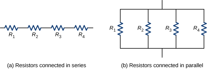
You just need to connect positive terminal of led with the one end of resistor and then connect another end of resistor with the positive terminal of battery. The symbols for a battery resistor and led are shown above. Analyzing simple series circuits with the table method and ohms law however the method we just used to analyze this simple series circuit can be streamlined for better understanding. In this circuit we will try to connect three 5mm white leds in parallel and light them up using a 12v supply.
Its not clearly shown in the schematic diagram but c1 should be a small 18 nf non polar capacitor. Circuit 3 of simple led circuits leds in parallel the final circuit in the simple led circuits tutorial is leds in parallel. Here is the circuit diagram for simple led circuit. On the circuit below the load resistor has been replace by a tuned circuit c4 and l1.
Fig A Simple Circuit R L Variable Load Resistor R S

Four Resistors And A 6 V Battery Are Arranged As Shown In The

Kirchhoff S Rules Physics
5 8 Building Simple Resistor Circuits Workforce Libretexts

Resistors In Series And Parallel Resistor Combinations
10 3 Resistors In Series And Parallel Physics Libretexts

Voltage Divider Article Circuit Analysis Khan Academy
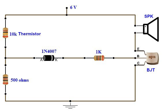
Simple Fire Alarm Circuit Using Thermistor Germanium Diode And Lm341

Lessons In Electric Circuits Volume Vi Experiments Chapter 3
