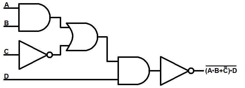
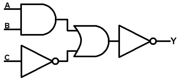
Simple Circuit Diagram Using Logic Gates
Logic Gates
How Cpus Are Designed And Built Part 2 Cpu Design Process Techspot

Https Encrypted Tbn0 Gstatic Com Images Q Tbn 3aand9gcs8gjghvhuehott9 Svdbrhf Mtjx5svoyj3qda8fjokcgifrhk Usqp Cau
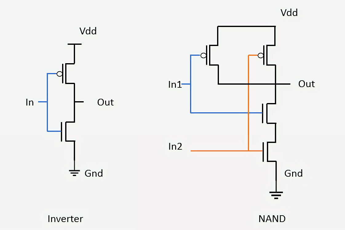
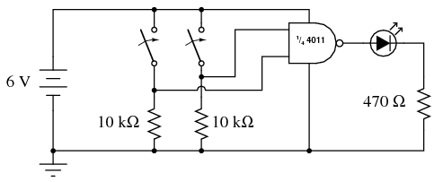
In essence this is like wiring two switches up in series.

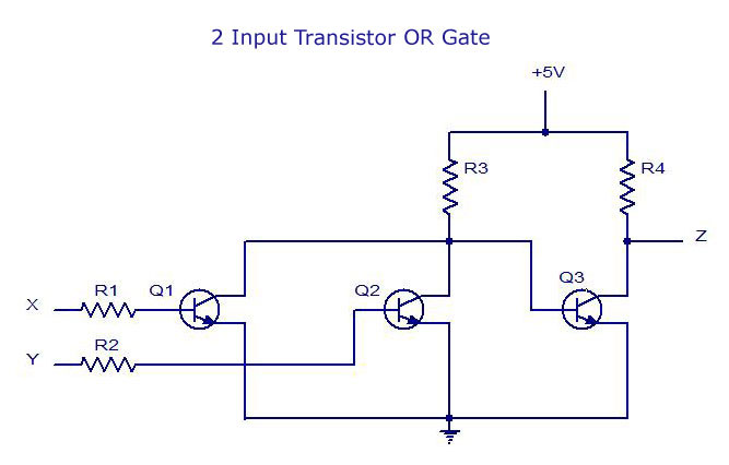
Simple circuit diagram using logic gates. In the circuit diagram above you can see a simple and gate built using two transistors. The basic idea involves driving a common cathode 7 segment led display using combinational logic circuit. To know more about boolean logic take a look boolean logic. 3v power supply is enough for the circuit.
I am going to show you how to make a 4 bit 0 15 adding calculator using 74xx series ic chips. In this article im going to show you a circuit diagram of calculator using logic gates and steps to create your own calculator using logic gates. Yes i realize my artistic skills never left the second grade. Picture of our logic gate project logic gates are primarily implemented using diodes or transistors acting as electronic switches.
Most logic gates can be made quite easily with transistors. And logic gate is a digital logic gate designed for arithmetic and logical operations every electronic student must have studied this gate is hisher career. Using karnoughs map logic circuitry for each input to the display is designed. But if you are a human then this is only a fun project.
You will need just a resistor and a capacitor to build an oscillator from these gates. Practical circuits using nand gates. Face recognition using eigen values 2. A brief introduction to boolean logic with a demonstration of traffic lights automated by a relatively simple logic circuit.
Principle of display decoder circuit. I apologise for the shaky footage but it was taken from my phone. So in calculators computers and manly digital applications use this gate. Or gate and gate and 3rd is not gate.
This article explains the basic logic gates like not gate and gate or gate nand gate nor gate exor gate and exnor gate with their corresponding truth tables and circuit symbols. Here we will use the very versatile ic 4093 which is comprised of 4 nand gates schmitt trigger and see how we can wire them up into a few amazing yet simple circuits. If you wish you can directly fix the buzzer without using relay. This gate is mainly used in applications where there is a need for mathematical calculations.
Leds as indicator used to show output level high1 or low0. The logic circuit is designed with 4 inputs and 7 outputs each representing an input to the display ic. We have made three basic logic gate using diode and npn transistor. Based on the rating of the relay that you are using in your circuit value of the battery will vary in the range of 6 15v.
We are using the relay in our circuit because if anybody wants to connect the alarm directly with the ac then also it will work without making any damage. Current does not flow to the output unless both switches are closed.

April 2010 Tiktak S Projects
Logicblocks Digital Logic Introduction Learn Sparkfun Com

Circuit Diagram Of Calculator Using Logic Gates
Logic Gates Types Working Principle Application Advantage
Lessons In Electric Circuits Volume Vi Experiments Chapter 7
Digital Electronics Logic Gates Basics Tutorial Circuit Symbols
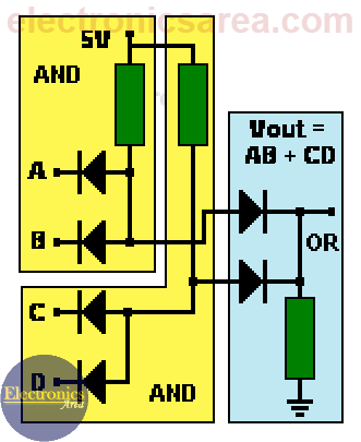
Or And And Logic Gates Made With Diodes Electronics Area

Logic Gates Project For Students Class 12

Electrical Symbols Logic Gate Diagram
