Simple Light Switch Circuit Diagram
Lighting Circuits Connections For Interior Electrical Installations
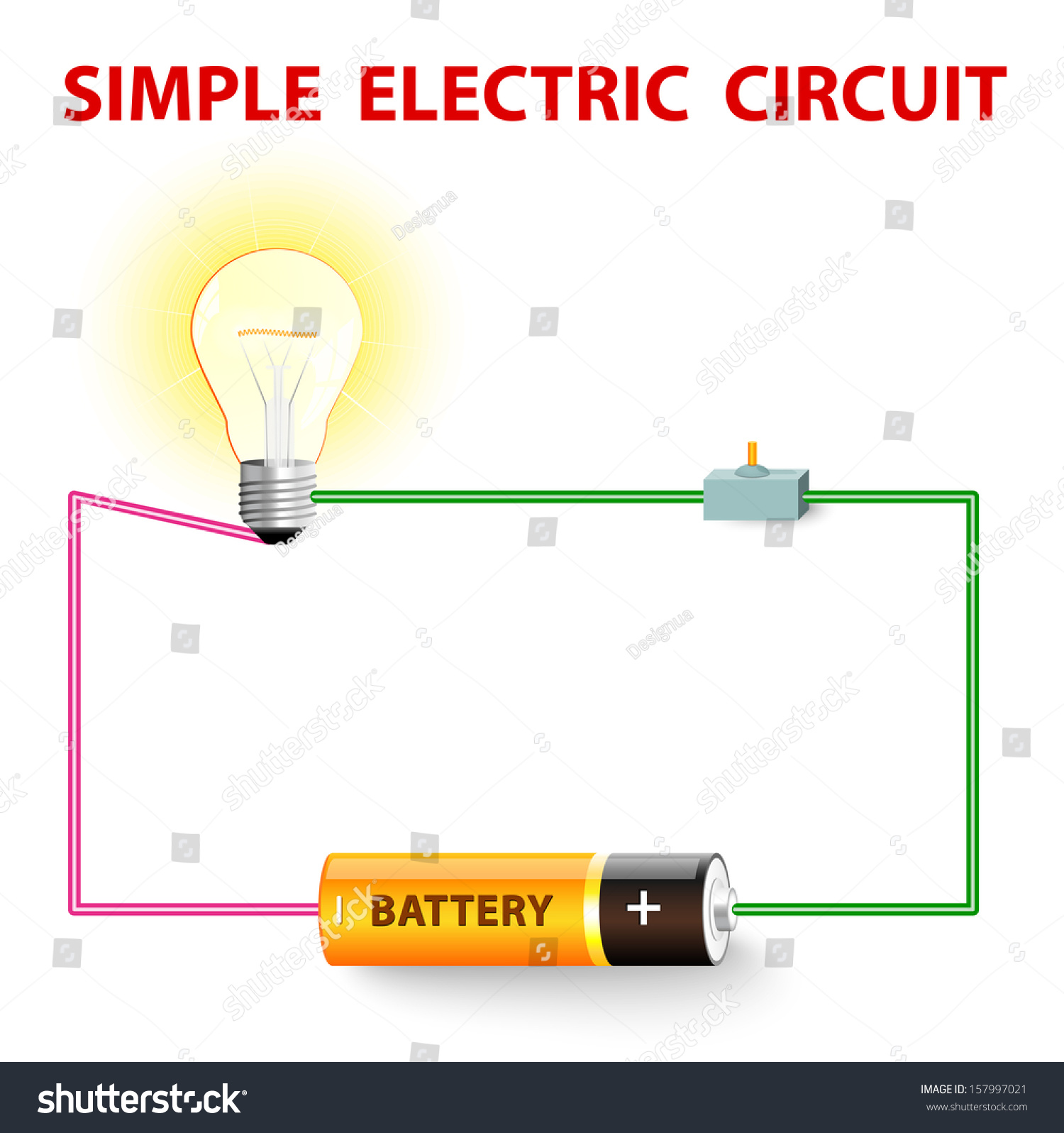
Simple Electric Circuit Electrical Network Switch Stock Vector
How Are Nand Gate And Nor Gate Represented With Switches And Lamps
Hey doing it yourself is great but if you are unsure of the advice given or the methods in which to job is done dont do it.
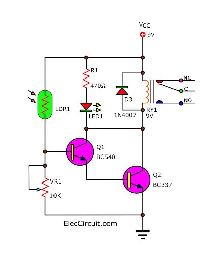
Simple light switch circuit diagram. I had added more pictures on how the wires connect to the bulb battery and switch 1311 battery insulated wire light bulb ducktape onoff switch read more. As you can see in the ldr circuit diagram it can be a distinguished as two smaller circuits. Electric circuits like ac lighting circuit battery charging circuit energy meter switch circuit air conditioning circuit thermocouple circuit dc lighting circuit multimeter circuit current transformer. Because the electrical code as of the 2011 nec update requires a neutral wire in most new switch boxes a 3 wire cable runs between the light and switch.
Light detector sensor circuit diagram. An electric circuit is a closed loop with a continuous flow of electric current from the power supply to the load. Wire a light switch in one way lighting circuits. Wiring a single pole light switch.
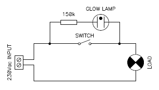
When ac mains is fed to the above circuit as per the setting of the pot c2 charges fully after a particular delay providing the necessary firing voltage to the diac. 1 light activated day night switch using transistors. The circuit can be used as a commercial automatic street light control system as a domestic porch light or corridor light controller or simply can be used by any school kid for displaying the feature in his school fair exhibitionthe following content describes four simple ways of making a light activated switch using different methods. The red and black are used for hot and the white neutral wire at the switch box allows for powering a timer remote control or other programmable switch.
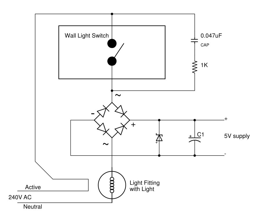
A simple lighting circuit is where the light switch is installed between the supply and the light fitting. A voltage divider made using ldr ldr1 and a potentiometer rv1 b output led d1 in our switching circuit made using a transistor bc547 q1. Wring a simple lighting circuit might be an easy enough process for a qualified electrician and with a little determination anybody with basic skills can do it. In this relay circuit we use a push button to trigger a 5v relay which in turn complete the second circuit and turn on the lamp.
This light switch wiring diagram page will help you to master one of the most basic do it yourself projects around your house. Lets take a simple example where we will be turning on an ac lamp by using a relay switch. First lets have a look at this wiring diagram describing a lighting circuit in its most basic form. Simple light dimmer switch circuit the circuit diagram shown above is an classic example of a light dimmer switch where a triac has been utilized for controlling the intensity of light.
This is an updated version of the first arrangement.

Why Smart Switches Can T Be Used Without Neutral Vesternet

Light Wiring Diagrams Light Fitting
Simple Electric Switch Diagram
Remote Controlled Light Switch Retrofit With Manual Override
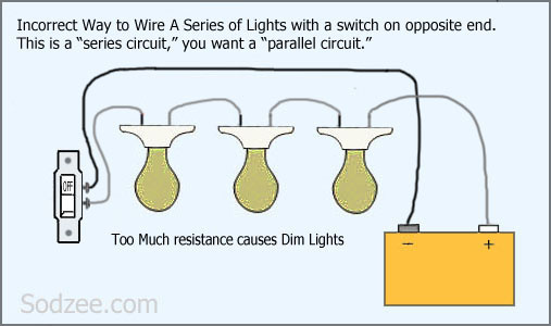
Simple Home Electrical Wiring Diagrams Sodzee Com

Light Sensor Circuit Diagram With Working Operation
Neon Glow Lamps More Than Simple Light Sources

Resources
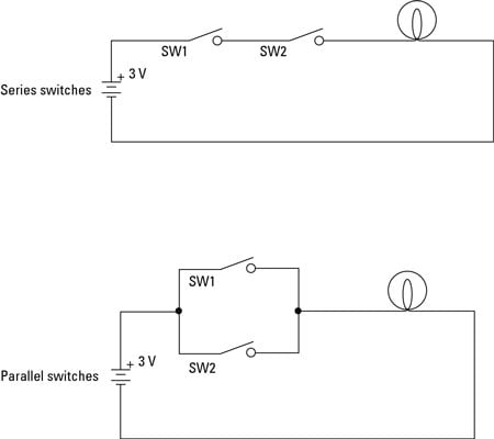
Electronics Projects How To Build Series And Parallel Switched
