Simple Series And Parallel Circuit Diagram
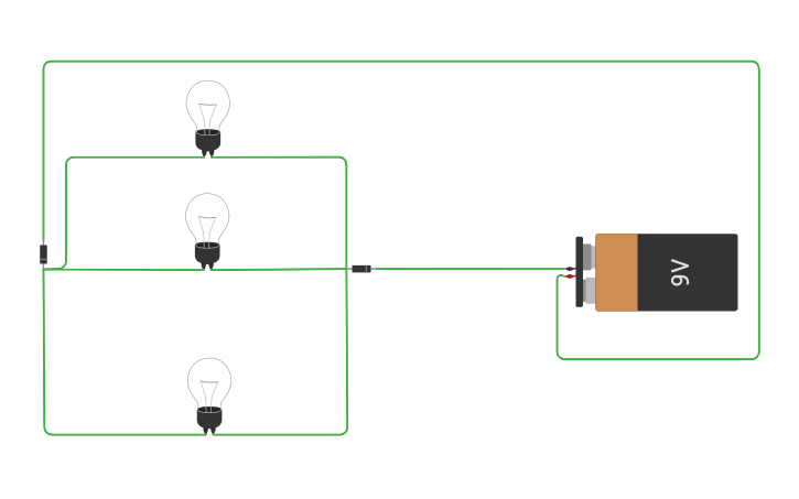
Simple Parallel Circuit Tinkercad

Resistors In Series And Parallel Resistor Combinations
Openphysics Dc Circuits Wikieducator
The main difference between series and parallel circuits is that in series circuits all components are connected in series so that they all share the same current whereas in parallel circuits components are connected in parallel so that they all have the same potential.
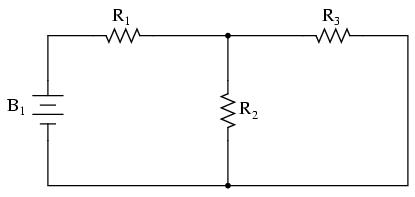
Simple series and parallel circuit diagram. Watch this video to learn more about series and parallel circuits. Figure 1 shows a circuit diagram of a very simple three resistor series parallel circuit. The two simplest types of circuits are the series circuit and the parallel circuit. And unlike a series circuit the lamps stay.
The circuit diagram for leds in parallel connection is shown in the following image. Components in a circuit can be connected in series or in parallel. Series and parallel circuits. In a simple parallel circuit all points are electrically common in one of two sets of points.
Simple circuits ones with only a few components are usually fairly straightforward for beginners to understand. Schematic of a dc circuit with three resistor in series. In this circuit we will try to connect three 5mm white leds in parallel and light them up using a 12v supply. Main difference series vs.
By using a table to list all voltages currents and resistance in the circuit it becomes very easy to see which of those quantities can be properly related in any ohms law equation. An electric circuit is a pathway made up. Resistors r 2 and r 3 are seen to be connected in parallel and resistor r 1 is in series with the parallel combinations of r 2 and r 3. Circuit 3 of simple led circuits leds in parallel the final circuit in the simple led circuits tutorial is leds in parallel.
What series and parallel circuit configurations look like. In a parallel circuit if a lamp breaks or a component is disconnected from one parallel wire the components on different branches keep working. For our example circuit the wire connecting the tops of all the components will have one node number and the wire connecting the bottoms of the components will have the other. Every device in a dc circuit whether a light bulb or electric motor can be represented by an electric resistance or resistor usually when drawing a circuit diagram or schematic you use certain symbols for the battery and resistors.
Resistor and one 100uf capacitor in series as hooked up in the first diagram for this experiment.

Series And Parallel Circuits Wikipedia

Ty 9863 Simple Diagram Of A Parallel Circuit
Lessons In Electric Circuits Volume I Dc Chapter 10

Series Circuits Series And Parallel Circuits Siyavula
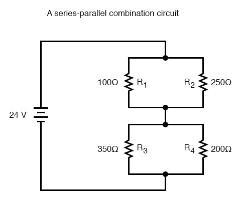
What Is A Series Parallel Circuit Series Parallel Combination

How To Solve Parallel Circuits 10 Steps With Pictures Wikihow
Https Encrypted Tbn0 Gstatic Com Images Q Tbn 3aand9gctqy5uuzfbl46sy0khxnj7d8ewtiapek 7ltchkschxfdtj6chw Usqp Cau
What Is The Difference Between A Series Circuit And A Parallel

Solving A Simple Circuit Diagram With A Single Voltage Source And
