Smart Valve Wiring Diagram
4 Wire Thermostat Wiring Color Code Onehoursmarthome Com
Https Content Spiraxsarco Com Media Spiraxsarco International Documents En Im Sp400 Im P343 37 En Ashx Rev 5a10aec0b88245ab986fb060cb016e4c

Honeywell Smart Valve Wiring Diagram Salus Port Valve Wiring
Eliminates injuries with the weight of the trailer fully resting on the landing gear and suspension the effort used in cranking the landing gear can result in injuries to the driver.
Smart valve wiring diagram. Heating controls wiring guide issue 17 v4073a y plan how a mid position valve operates within a y plan heating system how a w plan heating system operates. Our wiring diagrams section details a selection of key wiring diagrams focused around typical sundial s and y plans. To prevent property damage personal injury and or death if the vehicle must be raised do not work under the vehicle supported only by jacks. Wiring smart valve typical wiring diagram in atmospheric boiler.
With the pilot burner flame rod and check for good electrical connections through the pilot tubing if you have the main valve open and the main. The instrument senses valve position via a non contact hall effect. The hydro rain b hyve pro wifi sprinkler controller lets you monitor and control your customers use smart watering manual or a combination of both. 712019 to prevent personal injury and or death always wear safe eye protection when performing vehicle maintenance.
In this hvac diagnosis video i go over the ignition troubleshooting of a smart valve ignitor and flame sensor by honeywell. Wiring smart valve basic wiring diagram. Transformer switches thermostat and wiring. Step 6 check for the proper voltage at the control.
Master valve wiring not all systems have a master valve. Smartvalve smartvalve maximizes the grids transfer capacity so that our customers can. How to troubleshoot a honeywell smartvalve. I show the voltages of each of the wires connected to the smart valve.
Check that the vent damper is open. The icot is an instrument that derives its power directly from a control systems current loop. The icot smart valve positioner is an electro pneumatic servo system that continuously controls the position of a valve based on a 4 to 20 ma input signal. Installation materials smartvalve system controls.
A master valve is a normally closed valve installed at the supply point of the main line that opens whenever a zone is operatingit is normally labeled m mv or pump please note master valves should only be wired to the m and c terminals. Ik0300068 hadley smart valve troubleshooting guide page 2 of 5.

Digital Shower Installation Videos Customer Care

Life Smart Heater Wiring Diagram Diagram Base Website Wiring
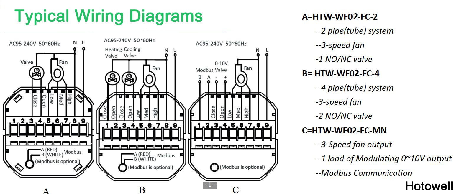
24v Smart Wifi Fan Coil Room Thermostat For Housing Application
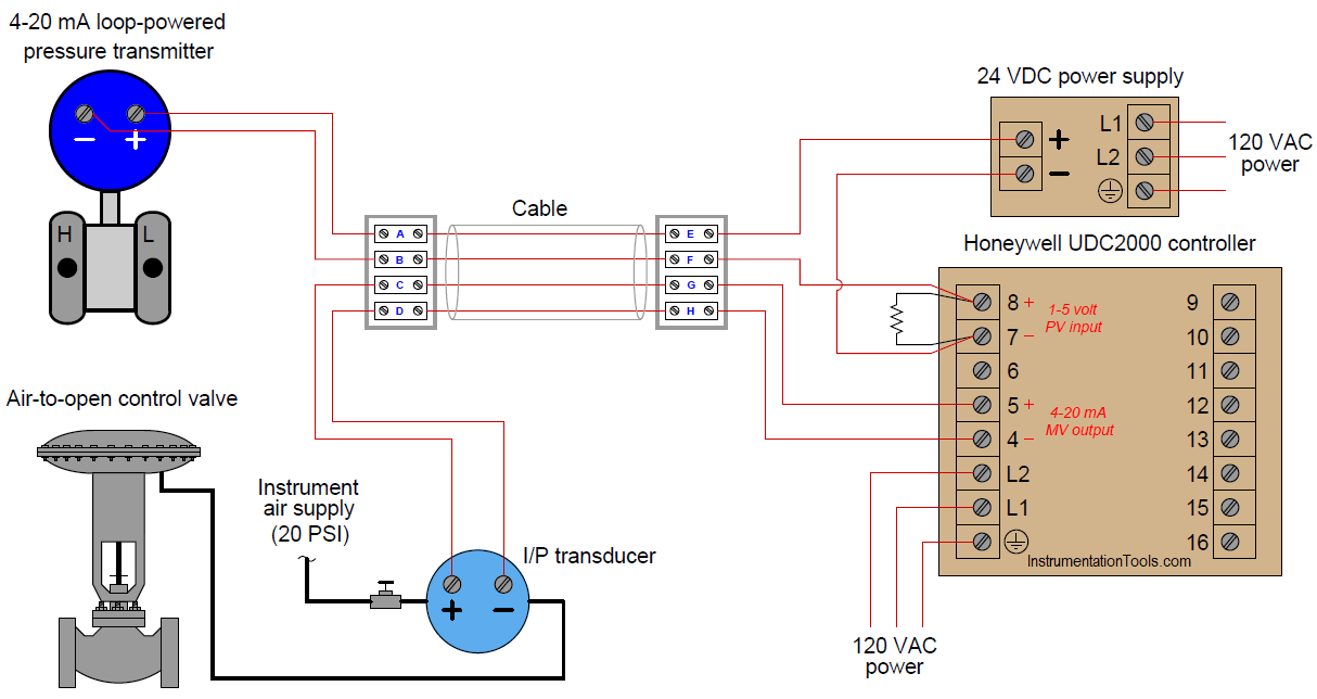
Pressure Control Loop Wiring Connections Instrumentation Tools

Millivolt Remote Control Guide Fireplaceremotecontrols Blog
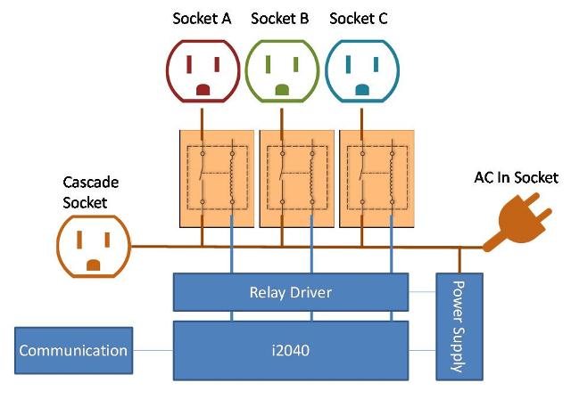
Wiring Diagram For Power Strips Gain Ak Rotterdamfeelgood Nl

Lx 3898 Honeywell Smart Valve Wiring Diagram Free Diagram

Sv9501m2031 U

Automatic Water Tap Faucet Valve Controller
