Solenoid Schematic

Schematic Circuit Diagram Of The Solenoid Switch Download

Solenoid Valve Piston With Pilot Design Z Tide Valve
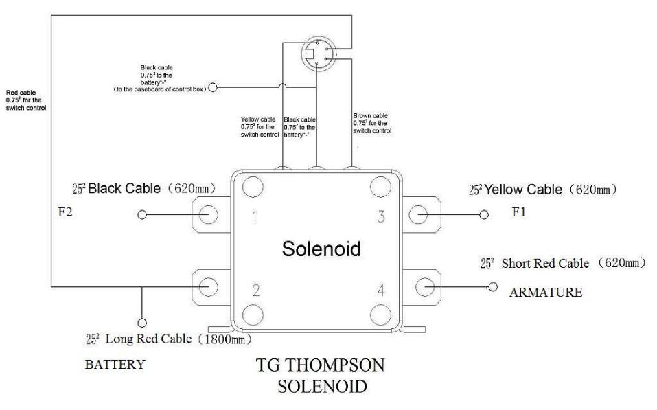
Dna Knowledge Base Tg Thompson Solenoid Wiring Diagram
It reveals the elements of the circuit as streamlined shapes and the power and signal links between the gadgets.

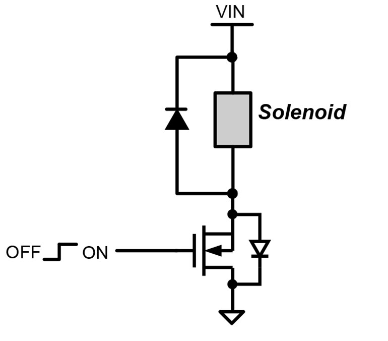
Solenoid schematic. The solenoid draws a continuous current of 700ma when energised and a peak of nearly 12a so we have to consider these things while designing the driver circuit for this particular solenoid valve. These 2 way 3 way and 4 way solenoid valves can handle most fluid control applications and are now available with class i division 2 approvals we also offer a complete line of general service isolation pinch proportional valves and manifold assemblies for use in medical equipment analytical instrumentation and industrial applications. The levels of detail for process equipment relates to the schematic type produced. Valve ansi or iso schematic symbols and flow diagrams solenoid valves are widely used to control the flow of either a gas or liquid in many types of components or equipment.
And how they relate to solenoid valves and pneumatic equipment. This article deals with common solenoid valve and other pneumatic symbols giving a detailed view of pneumatic circuit symbols and their meaning. A wiring diagram is a streamlined conventional pictorial representation of an electrical circuit. When a pneumatic actuator requires air pressure applied to two different ports in order to move two different directions such as the case for cylinders lacking a return spring the solenoid valve supplying air to that actuator must have four ports.
A wiring diagram is a streamlined traditional pictorial representation of an electric circuit. Collection of 4 pole starter solenoid wiring diagram. These electrically operated control valves are typically employed in a two way or three way operation and are specified as normally closed or normally open in a de energized state. The circuit requires an input voltage vcc to actuate the solenoid as well as a control signal input from a controller function generator or timing circuit which switches a transistor.
Solenoid valve and common pneumatic system symbols. One for air supply p one for exhaust e and two for the cylinder ports typically labeled a and b. What is a 4 way solenoid valve. This circuit schematic demonstrates the simplest form of solenoid drive circuitry and may be used to actuate most solenoid operated valves and pumps on this website.
Understanding ansi iso schematic symbols for fluid power and pneumatic components are used to identify and graphically denote the function and operation of piped control systems. The complete circuit diagram for solenoid driver circuit is shown in the image below.
What S The Best Way To Drive A Solenoid Electronic Design
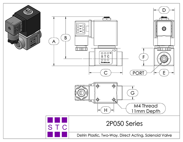
Solenoid Valve Specifications And Dimensions 2p050 Series

How 5 2 4 2 Way Pneumatic Valves Works A Buying Guide Tameson

M6800 Wiring Diagram Hamra Arabians De
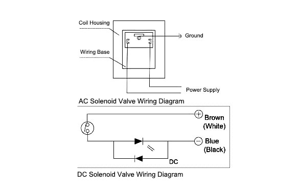
How To Wire A Solenoid Valve
Hyundai Kona Schematic Diagrams Emission Control System

Why We Require Dual Solenoids On A Control Valve

Lee Solenoid Valve Drive Circuit Schematics The Lee Company

How A 3 2 Way Pneumatic Valve Works A Buying Guide Tameson
