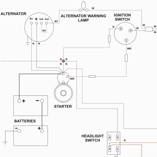
Starter Motor Wiring Connections
The starter system is simple and the checks on it are straightforward.

Starter motor wiring connections. If the starter does not turn the engine although the car battery is in good condition the fault may be a simple mechanical one or it may be an electrical one in the starter motor circuit. These solenoids are. The security starter relay controlled car starter wiring diagram is as shown in the following picture. They can also be found in large residential complexes and appliances requiring a large amount of power.
3 phase wiring for dummies understanding motor connections three phase systems are extremely common in industrial and commercial settings. Electrical checks are made with a circuit tester or test lamp or with a voltmeter. Most on starter solenoids are easy to wire as you mount the starter on the engine. The first part deals with the power circuit connections because starters consume and alternators produce great amounts of power.
Before the engine starts the alternator does not generate electricity the voltage of the neutral tap n binding post is zero no current passes through the charge light relay starter relay coil and charging indicator relay contacts are connected to ground. Starters are turned on and off and alternator output is. The process for wiring a starter and an alternator on a car is divided into two parts. Other solenoids mostly on fords are remote mounted.
In this video we cover the differences between a factory gm starter and an after market high torque mini starter. Often this might cause a loud screeching noise when starting the car. Another symptom is when the starter motor runs but fails to turn over the engine. Most vehicles use a starter mounted solenoid that functions as a high power switch to connect the starter drive pinion gear with the flywheel to start the engine.