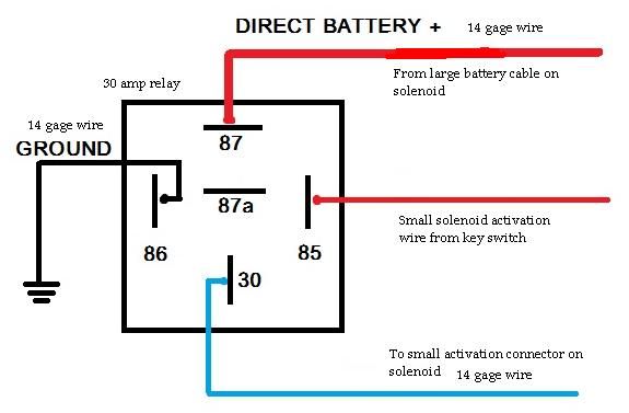
Starting Relay Wiring Diagram
Variety of 12 volt solenoid wiring diagram.

Starting relay wiring diagram. Knowing the sequence of operation for this type of starting relay can help you diagnose confirm or rule out certain service problems. 800 x 600 px source. 3 typical car starting system diagram the typical starting system wiring diagrams can divide into non relay control type single starter relay control type and security starter relay control type. A wiring diagram is a streamlined conventional pictorial representation of an electrical circuit.
Each component ought to be set and connected with other parts in specific manner. Refrigerator start relay wiring diagram refrigerator start relay wiring diagram every electric arrangement is made up of various unique components. Check the starter relay wiring one more time and then test by attempting to start the vehicle. Check for 12 volts at the relay input to the coil with the meters negative on the frame of the vehicle.
In the second video ill be going. Collection of 4 pole starter solenoid wiring diagram. A wiring diagram is a streamlined standard pictorial representation of an electrical circuit. How to wire a 12v ignition switch engine start push button 3 toggle panel with indicator light duration.
L1 and l2 are designated as the two connection points representing the two electricity flow path inherent with single phase circuits where a single phase supply voltage is fed to the motors internal circuit. John smith 85385 views. If the vehicle wont start check for a strong click from the relay when it is initiated. It reveals the elements of the circuit as streamlined shapes and the power and signal links between the gadgets.
Single phase motor wiring diagram with capacitor start capacitor run. It reveals the parts of the circuit as streamlined forms and the power as well as signal links between the devices. Or you are a trainee or maybe even you who simply want to know regarding typical starter relay wiring diagram kubota. A lot of folks out there have riding mowers.
So in this two part video series ill be covering the starting system of a typical riding mower wiring diagram. If not the arrangement wont work as it should be. Whatever you are we aim to bring the content that matches just what you are searching for. The coil is wired between terminals 2 and 5.