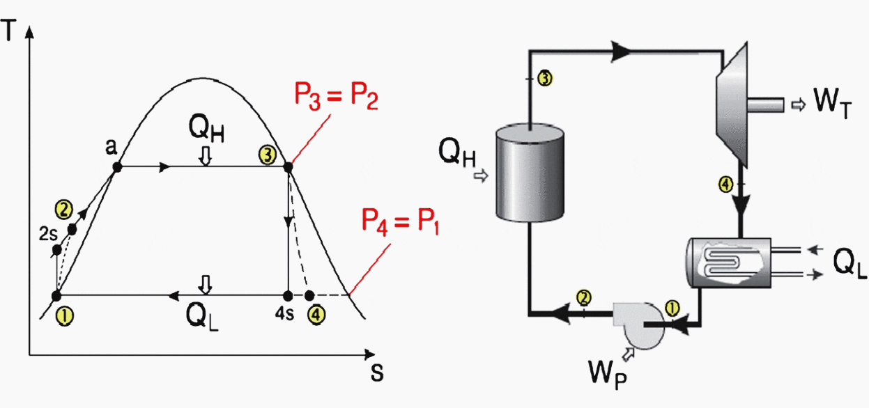
Steam Power Plant T S Diagram
Show the cycle on a t s diagram with respect to saturation lines and determine i.

Steam power plant t s diagram. If the plant uses 04 kgs of steam find the rate of. In this reheat cycle steam is expanded isentropically to an intermediate pressure in a high pressure turbine stage i and sent back to the boiler where it is reheated at constant pressure to the inlet temperature of the high pressure turbine. The t s diagram for an ideal steam power plant is shown where the high and low pressures are 10 mpa and 20 kpa respectively. Working principle of steam power plant here is the layout of a steam power plant working fluid cycle steam power plant is a closed cycle which uses the same fluid repeatedly.
On the ts diagram above state 3 is at a border of the two phase region of steam and water so after expansion the steam will be very wet. The pressure enthalpy p h diagram the common method of describing steam power plant systems is by plotting them on a t s temperature entropy diagram for steam. The quality of the steam at the turbine exit ii. The thermal efficiency of the cycle iii.
Simple vapor cycle and its components. A dry steam power plant is suitable where there is geothermal steam that is not mixed with water. By superheating state 3 will move to the right and up in the diagram and hence produce a drier steam after expansion. Chapter 2 steam power plant cycles.
Production wells are drilled down to the aquifer and the superheated pressurized steam 180350 0c is brought to the surface at high speeds then passed through a steam turbine to generate electricity. Learn about ts diagram of water and its thermodynamic terms by easy to understand lecture. First the water is filled into the boiler to fill the entire surfac. Steam leaves the condenser as a saturated liquid at a pressure of 10kpathe isentropic efficiency of the turbine is 80 percent and that of the pump is 95 percent.
In this video you will learn. This is done exclusively in all thermodynamic text books that i have evaluated over many years. Boiler turbine condenser pump carnot cycle for steam disadvantages of carnot cycle application.