Strobe Wiring Diagram

Strobe Light Wiring Diagram Faint Repeat24 Klictravel Nl
Led Strobe Circuit 555
92e09a Strobe Lights Wiring Diagram For Cars Wiring Library
A wiring diagram is a streamlined standard photographic depiction of an electrical circuit.

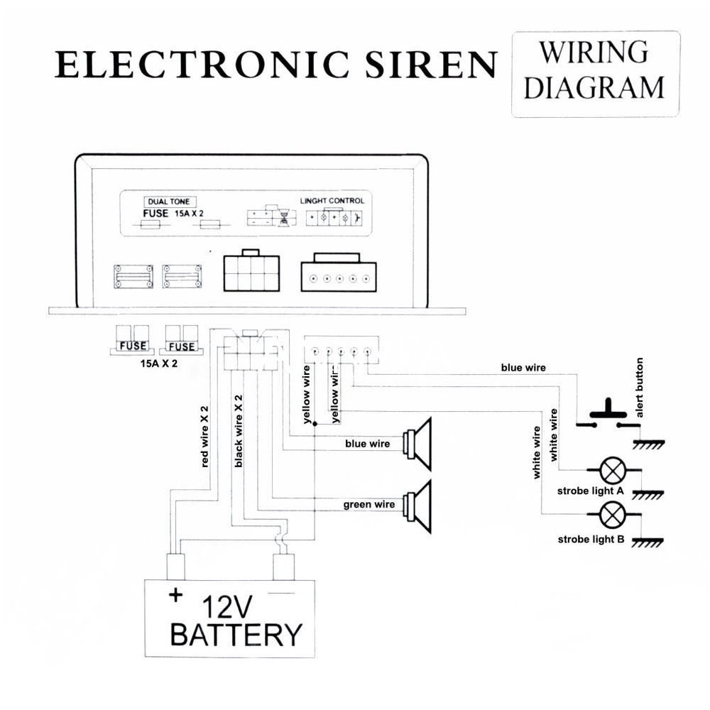
Strobe wiring diagram. The 2 wire products fit systems where a single nac controls both horn and strobe. The strobe circuit is dangerous and the internal wiring can kill you on contact. Connecting the skybeacon to a high voltage strobe power supply will damage the skybeacon. Let me know.
Strobe products are available in two versions. It shows the components of the circuit as simplified shapes and the power as well as signal connections between the devices. If a sync cord is attached to the strobe for example the diagram indicates which pins on the other end of the cord can be connected with a paper clip to test the strobe functions. The 4 wire products are in tended for systems which have separate wiring circuits for the horn and strobe.
Assortment of 3 wire strobe light wiring diagram. Fire alarms explained is a series where zach discusses basic concepts of fire alarm systems as well as showing the specific systems hands on. The diagrams below show both the incorrect and correct wiring for utilizing skybeacon with an existing anti collision system. Wiring diagrams test firing strobes use the appropriate diagram below to help in testing and analysis of ikelite sync cords and strobes.
The strobes remain flashing refer to the wiring diagram fig1 yr dba refer to table 1. Strobe wiring diagrams the skybeacon should never be connected directly to a high voltage strobe power supply. This latter point cannot be stressed enough. A wiring diagram is a simplified traditional photographic representation of an electrical circuit.
All spectralert advance products are suitable for use in synchronized systems. It reveals the components of the circuit as streamlined shapes as well as the power as well as signal links in between the gadgets. The pot remote input connector the bodies of all or any switch and all exposed metalwork including the strobe reflector must be connected to safety earth via a 3 core mains cable.

18e18w 3 Way Switch Wiring Wire 12 Volt Reversing Motor Diagram Hd

Federal Signal Wiring Diagram Auto Electrical Wiring Diagram

Cat 5714 Sdm 240 Select A Horn Strobe Sync Module En Manualzz
Strobe Lights Wiring Diagram For Cars Wiring Library

C657c0b A 3 Wire Strobe Bulb Wiring Diagram Manual Book And

Strobe Lights Png Picture 737231 Strobe Lights Png

Police Lights Wiring Diagram Roti Dego11 Vdstappen Loonen Nl

488 Wiring Diagram Whelen Edge Lfl Wiring Library

Es 8056 Strobe Lights Wiring Diagram For Cars Free Diagram
