Switch And Receptacle Wiring

How To Wire A Switch Light Then Switch Then Outlet

Tracing 3 Wire Circuits Jlc Online

Mh 7867 Wiring A Loop Light Switch Download Diagram
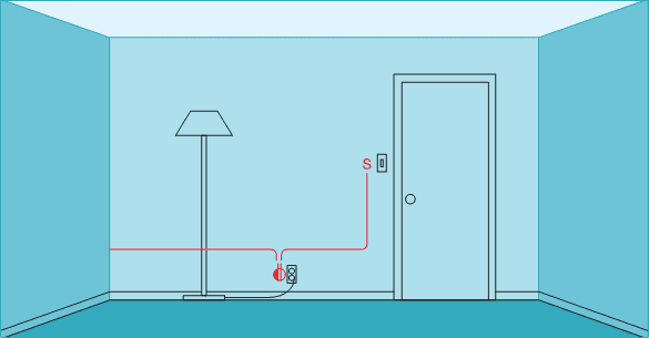
This is commonly used to turn a table lamp on and off when entering a room.

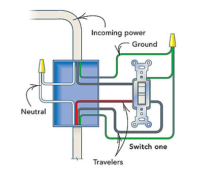
Switch and receptacle wiring. Outlets are split wired so that the top half of the receptacle is live all of the time and the bottom of the receptacle is controlled by the wall switch. With this wiring both the black and white wires are used to carry 120 volts each and the white wire is wrapped with electrical tape to label it hot. In this case the circuit load flows both to the receptacle and to any downstream receptacles without being dependent on flowing through the receptacles connecting tab. In this diagram 2 wire cable runs between sw1 and the outlet.
This way the outlet is wired and controlled onoff through the switch. The second method of wiring a mid run receptacle is to connect the receptacle to the circuit wires with pigtails that tap into the circuit wires passing through the box. How to wire for and install a switch duration. Wiring a switch to an outlet.
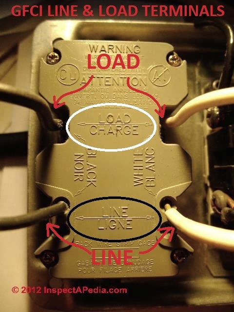
The second terminal of switch then connected back to the brass terminal of outlet. With levitons extensive assortment of combination devices you can fill a one gang space with two switches a switch and receptacle even a switch and gfci. The light onoff operation can be controlled through the gfci switch while the ordinary outlet is directly connected to the gfci load terminals. The switchreceptacle combo device is set up like a duplex receptacle but has a 15a single pole switch in one half and a single 15a 125v receptacle in the other half.
Wiring a switch to a wall outlet. The outlet should be wired to a dedicated 20 amp240 volt circuit breaker in the service panel using 122 awg cable. Wiring a 20 amp 240 volt appliance receptacle. They can work in conjunction with one another or they can be connected and used independent of each other.
How to wire a double receptacle two different ways. Switched receptacle outlet wiring diagram depicting the electrical power feeding into an electrical receptacle box and then going to a switch and to another receptacle. Wiring a gfci combo switchoutlet with protected light outlet receptacle in this special case wiring diagram both light and ordinary outlet is connected to the load terminals of gfci. Wiring a receptacle to a switch receptacle always on if power is coming into the switch box from the panel and you want to connect an outlet to the switch your first option is to wire the receptacle to always be on.
From sensor guide lights to multi. In this wiring a switch is added to to an existing outlet by removing the hot wire from outlet brass terminal and connected to the first terminal of switch. This outlet is commonly used for a heavy load such as a large air conditioner.
82eb9ef Outle Switch Wiring Diagram 3 Wiring Library
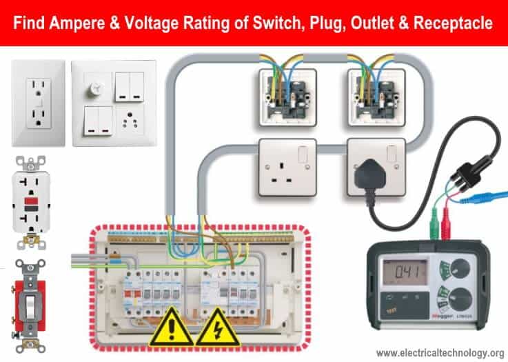
Find Voltage Ampere Rating Of Switch Plug Outlet Receptacle
31 Common Household Circuit Wirings You Can Use For Your Home

How To Install Dimmer Switches Home Electrical Wiring Diy

Smart Light Switch Wiring Diagrams Mr Electrician

Switched Outlet Wiring Diagrams Mr Electrician
Back Wired Electrical Receptacle Switch Connectors Safe Or Unsafe

Hook Up Light Switch Receptacle How To Wire A Switch Receptacle
How Do I Add A Three Way Switch To A Receptacle Fine Homebuilding
