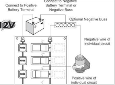
Switch Panel Wiring Diagram
Bass Pro Shops Rocker Switch Panels Bass Pro Shops
2
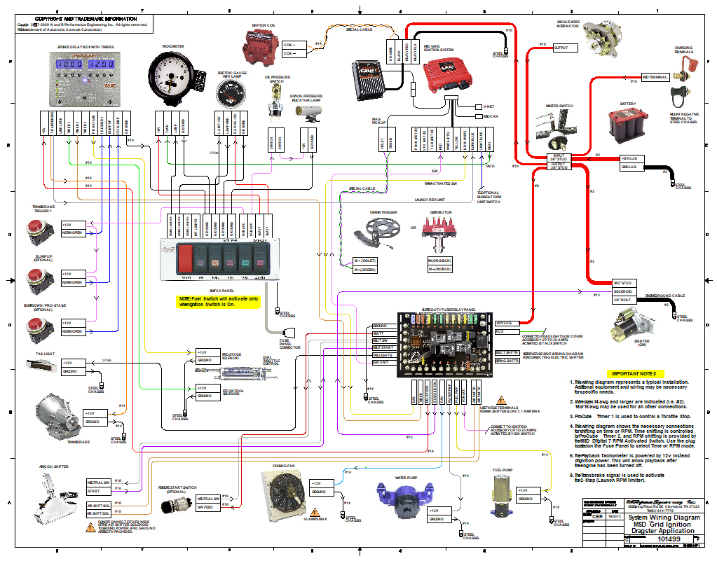
Manuals K R Performance Engineering
The switch panel and separate fuserelay panel are interconnected with a cable assembly that simply plugs in.
Switch panel wiring diagram. 2 usb ports are sufficient to meet charge demand. It reveals the components of the circuit as simplified forms and the power and also signal links in between the devices. Digital voltage display helps to monitor vehicle. 12v switch panel wiring diagram youll need an extensive professional and easy to understand wiring diagram.
Rear panel space allowance from outside edge to socket hardware is 10mm circumference all four sides. Or these terminals can be ignored for non backlit switch banks. A wiring diagram is a simplified traditional pictorial depiction of an electric circuit. Mount the relay panel assembly in a convenient location usually near the ignition box and connect the switch panel connector.
Corner securing holes 4mm dia for countersunk screws. Collection of painless wiring switch panel diagram. 180mm x 110mm. Wiring diagram for race car kill switch in addition it will feature a picture of a sort that could be observed in the gallery of wiring diagram for race car kill switch.
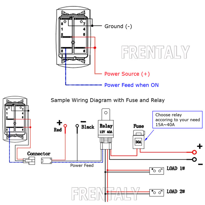
With the switch on there should be continuity from one 38 stud to the other 15 ohms or less resistance. These leads will go to the switch panel in the cockpit. With this kind of an illustrative guide youll be capable of troubleshoot avoid and total your assignments easily. This eliminates the clutter of wiring to switches and relays along with saving tons of time.
Keep in mind that the longer your wiring run from the battery to switch panel is the more voltage drop youll have more about voltage drop. When wiring this switch you can choose if youd like to illuminate it because of the independent lamp attached to terminals 8 and 7. Depth of entire panel with wiring sockets and switches allow 70mm minimum. Prevent voltage drop by using larger cable.
Boat switch panel with marine grade rocker switches and rubber seal cap to keep it water tight.
Wiring Diagram For Older Boat Continuouswave
Ovsp21220wi Smart Switch Panel User Manual Orvito

Float Switch Installation Wiring Control Diagrams Apg
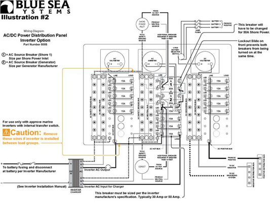
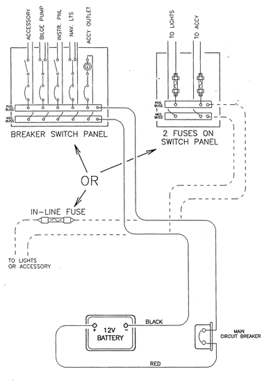
Wiring Inverter Load Group Sub Panels Blue Sea Systems

Touch Switch Smart Light Switch Panel Tech Giants

Smart Light Switch Wiring Diagrams Mr Electrician

Instructions

Panel Push On Ignition Switch Wiring Diagram Tukir Www Kultur Im

How To Install A Smart Light Switch Digital Trends
