System Engineering Context Diagram

Context Diagram An Overview Sciencedirect Topics
28 Context Diagram Visio System Context Diagram
Context Diagram Symbols
A system context diagram scd in engineering is a diagram that defines the boundary between the system or part of a system and its environment showing the entities that interact with it.

System engineering context diagram. The flows on a context diagram also provide prompts when engineering requirements. Definition 1 describes the reason for considering context. Definitions 2 relates context to a context diagram. Since a context diagram is a specialized version of.
The context diagram shows the system under consideration as a single high level process and then shows the relationship that the system has with other external entities systems organizational groups external data stores etc. System and the terminators. Each flow on the context diagram has to be consumed or generated by the system of interest. A context diagram also known as a system context diagram or level 0 dfd communicates a high level overview of the flow of data within a technical system.
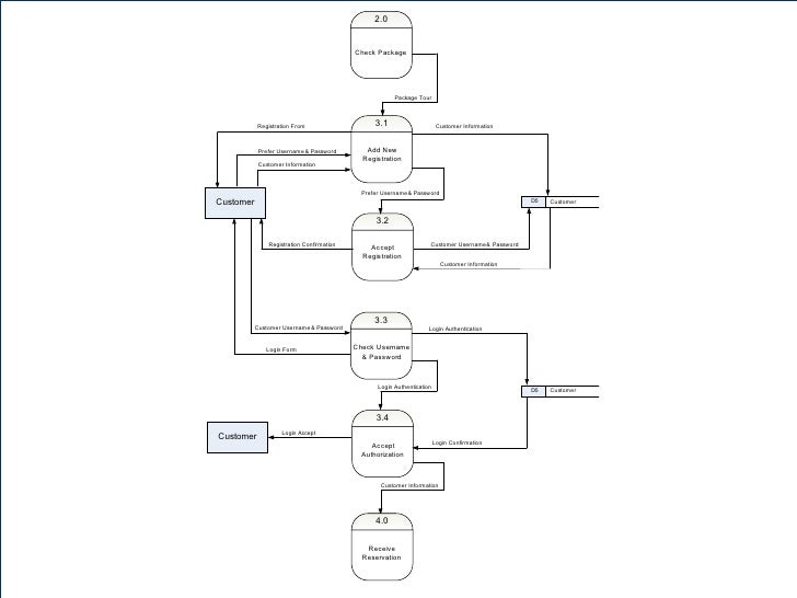
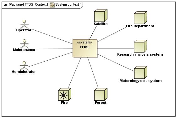
The system context diagram also known as a level 0 dfd is the highest level in a data flow diagram and contains only one process representing the entire system which establishes the context and boundaries of the system to be modeled. A context diagram is used to depict the environment in which the system under design has to operate. As we note in kossiakoff sweet seymour and biemer systems engineering principles and practice system context diagrams represent all external entities that may interact with a systemsuch a diagram pictures the system at the center with no details of. This is most common way in which context is express in systems engineering.
With virtually no technical knowledge required to understand this type of system diagram engineers analysts developers and stakeholders can easily use it as a visual reference for systems analysis and design. A number of context diagram notations are available. The entire software system is shown as a single process. By questioning how this is to be achieved will help uncover the systems functional requirements.
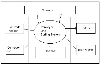
It identifies the flows of information between the system and external entities ie. Another name for a context diagram is a context level data flow diagram or a level 0 data flow diagram. This diagram is a high level view of a systemit is similar to a block diagram. It is usually drawn as a bubble for the system and the entities that interact with the system both human and computers around it connected to the system with lines.
Systems context diagrams are a fundamental early product that systems engineers need to develop to get the program started off right. A context diagram is a simple birds eye or helicopter view of a system of interest. The systems engineering tool box. A context diagram sometimes called a level 0 data flow diagram is drawn in order to define and clarify the boundaries of the software system.

Mission Thread Analysis Using End To End Data Flows Part 1
How To Model A Simple System Context With Sysml Model Based

Block Diagram Linux Kernel Computer Software System Context
Systems Engineering Overview Sebok

Software Engineering Introduction To Software Engineering Ppt
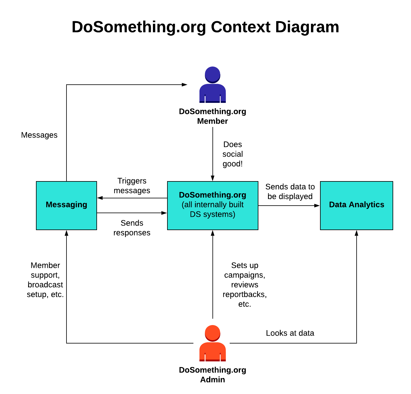
Documentation Dosomething Org
Https Www Icas Org Icas Archive Icas2018 Data Papers Icas2018 0821 Paper Pdf

9 2 1 3 Modelling Software Design And Development
Software Engineering Is
