Traffic Light Wiring Schematic

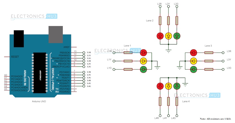
4 Way Traffic Lights Diagram Electronic Circuit Projects

Using Time Delay Relays To Cycle A Traffic Signal

The Proposed Traffic Light Preemption System Download
The schematic diagram of the traffic light circuit in update version.

Traffic light wiring schematic. Typically these lights allow or for bid traffic to use one or more of the. We know each traffic signal light setup will have three colors and representing red for stop yellow for wait and green for go those signals are works based on time intervals. I also wanted to try out an arduino controller and thought this would be a nice simple. I am a student with a homework assignment basic wiring with a timer etc.
Then this output frequency will appear at pin 3 of ic1 into pin 14 of ic2. I always wanted an old traffic signal and finally got one recently. Traffic signal lights are very important to regulate vehicles and traffic on roads simple four way traffic light circuit is designed with timer ic 555 and counter ic cd4017. 1 1 light yellow and red lights 0 0 light turned green according to the nature of the gate nor examples of traffic light sequence apply only to one lane for traffic light circuit that uses more than one line then you can use the same circuit device and use a combination of gates as a liaison between the conditions of each lane.
I got an old traffic light from a dot near my hometown. This is an amateur video on how to wire up a traffic light or stop light to plug in the wall at your home. What fun is that. The timer generates pulses and these pulses are fed to the ten stage decade counter.
Pete vree 388961 views. In this traffic light project we are going to design a circuit to control traffic lights on a four way signal. 50 videos play all mix traffic light diagram using time relay magnetic contactor youtube ladder diagram basics 1 duration. I took the thing apart to clean it and see if i could get it working.
In the oscillator ic1 is connected as the astable multivibrator circuit to generate the frequencies. Wiring an old traffic light. A line diagram 120 volt traffic light using hard wiring not plc or solid state circuits i did not explain myself very good in my question. However it was very simply wired so that all the lights were fixed on.
This circuit is designed by 555 timer ic timer and a decade counter. I was surprised to find that the bulb on the green and red lights had been replaced with an led unit. Lane control lights are a specific t ype of traffic light used to manage traffic on a mu lti way road or highwa y.
Arduino Traffic Light Controller
Daisy Chain Wiring Diagram Traffic Signals Online Wiring Diagram
Schematic Traffic Light Relay Circuit

National Traffic Signal Specifications Pdf
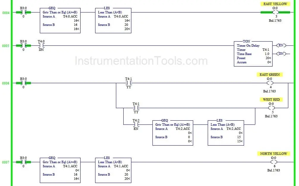
نصف السعر وسيم صور جديدة لل Plc Ladder Diagram For Traffic Light
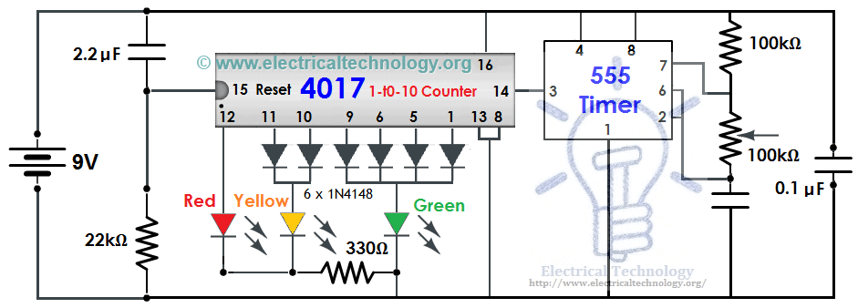
Traffic Light Control Electronic Project Using 4017 555 Timer
Https Www Dot State Pa Us Public Pubsforms Publications Pub 20149 Pdf
Traffic Light Circuit Using Relays
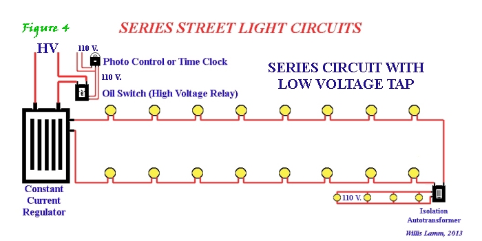
Energy Saving In The Street Lighting Control System A New Approach
