Trailer Brake Plug Wiring Diagram
2fd59 7 Blade Trailer Wiring Diagram Wiring Resources

Isuzu D Max Trailer Wiring Diagram Diagram Base Website Wiring
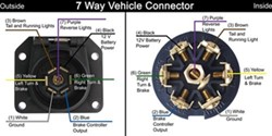
7 Way Rv And 7 Way Round Pin Brake Controller Output Wire
By law trailer lighting must be connected into the tow vehicles wiring system to provide trailer running lights turn signals and brake lights.
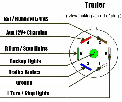
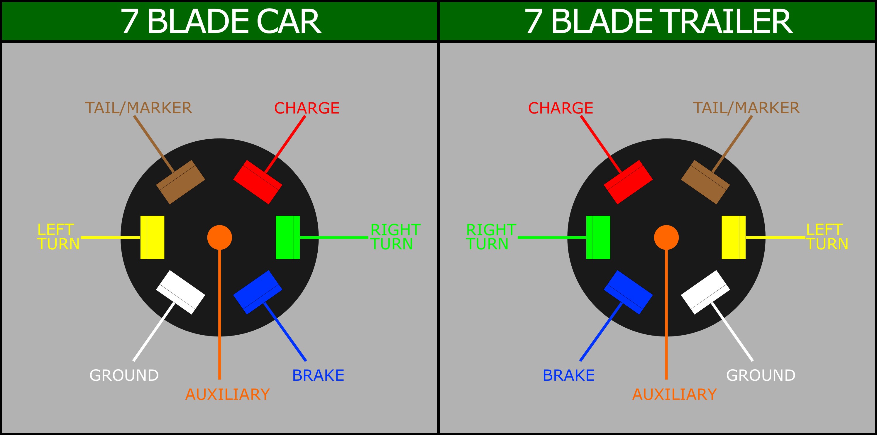
Trailer brake plug wiring diagram. Any vehicle towing a trailer requires trailer connector wiring to safely connect the taillights turn signals brake lights and other necessary electrical systems. This is accomplished by tapping into the tow vehicles electrical harness to transfer power to the trailer wiring system. The other thing that you will get a circuit diagram could be lines. 7 way plug wiring diagram standard wiring post purpose wire color tm park light green battery feed black rt right turnbrake light brown lt left turnbrake light red s trailer electric brakes blue gd ground white a accessory yellow this is the most common standard wiring scheme for rv plugs and the one used by major auto manufacturers today.
A circuit is usually composed by many components. Trailer connectors are used between the two to allow disengagement when not towing. Assortment of electric trailer brake wiring schematic. A wiring diagram is a streamlined conventional pictorial representation of an electric circuit.
Special light and wiring systems need to be installed on your tow vehicle before you can tow any trailer. It reveals the parts of the circuit as streamlined forms as well as the power and signal connections in between the gadgets. Elecbrakes must be connected to trailer wiring circuits as outlined in the wiring diagram. Tail light converters brake control wiring vehicles towed behind a motorhome wiring diagram for common plugs breakaway switches.
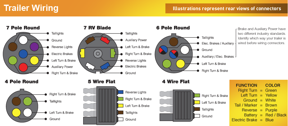
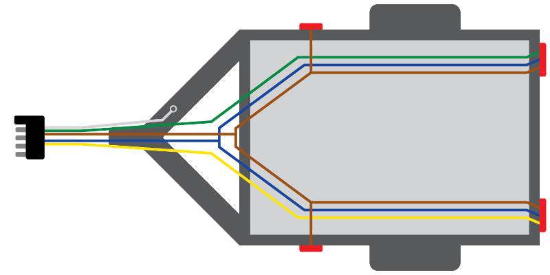
1 4 wire the first 4 pins white brown yellow green just like the 4 pin connector above. Wiring diagram comes with a number of easy to adhere to wiring diagram instructions. It really is supposed to assist all of the typical person in developing a correct program. 5 way trailer wiring diagram allows basic hookup of the trailer and allows using 3 main lighting functions and 1 extra function that depends on the vehicle.
An extra pin allows using another extra function. Ensure it is sealed off and cannot create a short circuit with any other wire or the chassis. Blue electric brakes or hydraulic reverse disable see blue wire notes below in the trailer wiring diagram and connector application chart below use the first 5 pins and ignore the rest. The first component is symbol that indicate electrical element from the circuit.
7 pin trailer wiring diagram with brakes amazing 7 wire trailer 7 pin trailer wiring diagram with brakes. Traditional trailer with brakes use a 5 pin connector. The service brake circuit must be disconnected from an existing trailer plug.

2012 F250 Wire Diagram For Trailer Giant Fuse4 Klictravel Nl

A518 Wiring

Etrailer Trailer Brake Controller Installation 2001 Dodge Ram
7 Pole Round Wiring Diagram Lan1 Repeat13 Klictravel Nl

Amazon Com Curt 58140 Trailer Side Rv Blade 7 Way Trailer Wiring
5 Point Trailer Wiring Diagram Giant Repeat1 Klictravel Nl
7 Way Trailer Wiring Diagram With Brakes
B4d8 Trailer Hitch Plug Wiring Diagram Wiring Library
5m22jmnfucvanm
