Trailer Connection Wiring Diagram

7 Pin Trailer Connector Wiring Diagram Diagram Base Website Wiring

Wrg 6242 Truck 7 Pin Trailer Connector Wiring Diagram

Wiring Diagram Ac Power Plugs And Sockets Trailer Connector
The 7 pin n type plug and socket is still the most common connector for towing.

Trailer connection wiring diagram. 4 way trailer connectors are. 1 2 3 4 5 6 7 wiring diagram tailgate trailer sabs 1327 1981 1 left indicator yellow 1 2 auxiliary blue 3 earth white. 7 pin n type trailer plug wiring diagram. They also provide a wire for a ground connection.
Or why not make your diy installation easier with our plug and play solutions. The four wires control the turn signals brake lights and taillights or running lights. We have an excellent wiring diagram on our website i will provide you a link so you can look at it. This has now been replaced by 13 pin euro plugs on all new caravans.
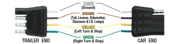
Pins 2 and 5 are not used on our standard range of trailers. Trailer wiring prescott trailers. 4 pin trailer wiring diagram. When wiring a trailer connector it is best to wire by function as wire colors can vary.
We recommend these standards because they are pretty universal. Trailer plug wiring diagram. 7 pin trailer wiring diagram with brakes 7 pin flat trailer wiring diagram with brakes 7 pin rv trailer wiring diagram with brakes 7 pin trailer wiring diagram with brakes every electrical arrangement is made up of various different parts. That said for specific situations there are industrial standards with different connectors and wire arrangements.
Below is the generic schematic of how the wiring goes. The diagram is the new zealand standard for the 7 pin flat trailer plug used on prescott trailers. The following trailer wiring diagrams and explanations are a cross between an electrical schematic and wiring on a trailer. If not the arrangement will not function as it ought to be.
As the name implies they use four wires to carry out the vital lighting functions. Above we have describes the main types of trailer wiring diagrams. If you are looking at the inside of the trailer connector where the wires mount to the terminals starting at the top and rotating clockwise. Our trailer wiring diagram is a colour coded guide designed to help you wire your trailer plug or socket.
Each component ought to be set and connected with different parts in particular manner. Venter nosecone and fridges. 4 way trailer connectors are typically used on small trailers such as boat snowmobile utility and other trailers that that do not use brakes.
5 Pin Round Trailer Plug Wiring Diagram
2f23 Ford F350 Wiring Diagram For Trailer Plug Wiring Library
Standard 7 Pin Trailer Wiring
7 Way Rv Trailer Connector Wiring Diagram Etrailer Com

Understanding Caravan And Tow Car Electrics Remolques

7 Way Trailer Plug Wiring Diagram Lan1 Anb3 Vmbso De
Trailer Wiring Diagram Wiring Diagrams For Trailers

Toyota Blade 2007 Wiring Diagram Diagram Base Website Wiring

Pole Travel Trailer Connector Wiring Color Code Trailer Wiring
