Transistor Amplifier Gain Formula
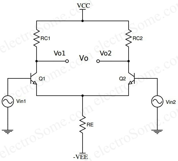
Differential Amplifier Using Transistors

Experiment Transistor Circuit Design
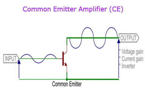
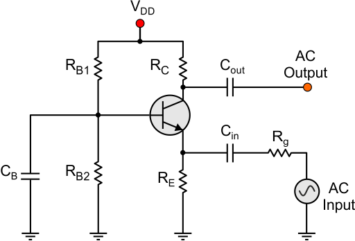
Npn Common Emitter Amplifiers
The equation above for beta can also be re arranged to make ic as the subject and with a zero base current ib.
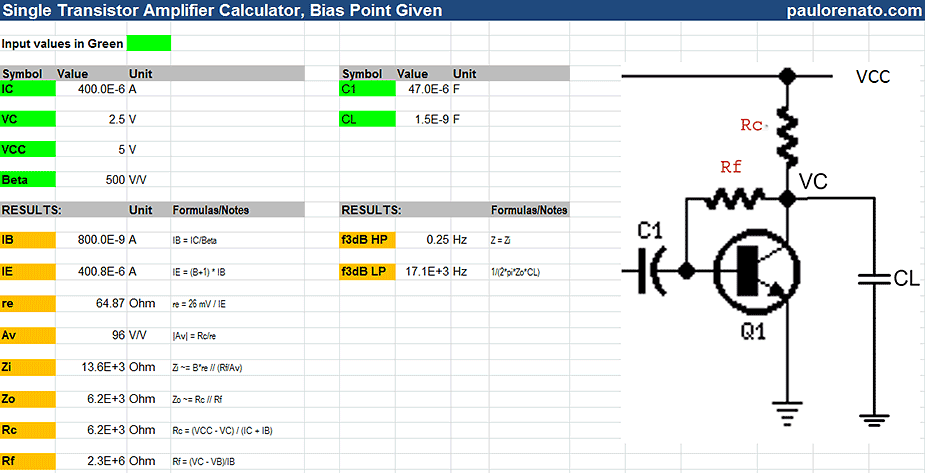
Transistor amplifier gain formula. Here common emitter fixed biased. In electronics gain is a measure of the ability of a two port circuit often an amplifier to increase the power or amplitude of a signal from the input to the output port by adding energy converted from some power supply to the signal. The below figure shows how a transistor looks like when connected as an. More in depth transistor gain equations and theory.
Z parameters are one of the basic parameters used when treating a circuit as a black box. It is sometimes useful to use some simple transistor theory to derive the gain calculations and formulas. This can lead to some confusion. The values of beta vary from about 20 for high current power transistors to well over 1000 for high frequency low power type bipolar transistors.
An common emitter amplifier circuit has a load resistance r l of 12kw and a supply voltage of 12v. A transistor is a three terminal semiconductor device and the terminals are eemitter b base c collectorthe transistor can work in three different regions like active region cutoff region saturation region. Common emitter amplifier example no1. The dc bias voltage applied to the emitter base junction makes it remain in forward biased condition.
This forward bias is maintained regardless of the polarity of the signal. Transistors are turned off while working in the cut off region and turned on while working in the saturation region. Basic transistor current flows. The value of beta for most standard npn transistors can be found in the manufactures data sheets but generally range between 50 200.
The most widely used circuit is the common emitter where the emitter is common to both input and output circuits. You need to replace the transistor with right model ill use mathremath model. With that resistor the gain will always be 10 for every circuit no matter if the particular 2n2222a is really capable of 100 or only 35. The reason for using h fe is that it refers to way of measuring the input and output parameters of a transistor.
Transistors work as an amplifier while they work in the. For example suppose the transistor gain range from 35 to 100 like the 2n2222a mentioned above you may choose the resistance value to get a gain of 10. It is usually defined as the mean ratio of the signal amplitude or power at the output port to the amplitude or power at the input port. 2n3553 transistor in a to39 metal can transistor gain derivation.
Now note that the gain mathav displaystyle fracvovimath alright now you need to calculate mathvomath and.
Common Emitter Amplifier Working Principle And Its Applications
Bjt Transistor Theory
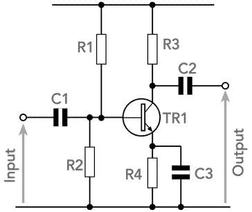
1 Common Emitter Self Biased Transistor Amplifier Circuit

Common Emitter Amplifier Electrical4u
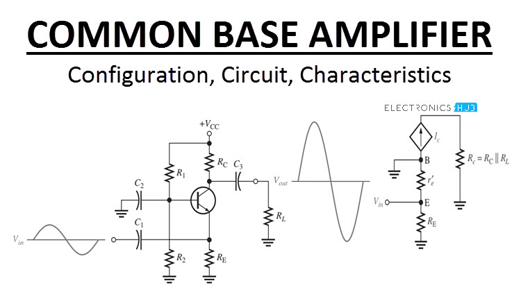
Common Base Amplifier Configuration Circuit Characteristics

Chapter 9 Single Transistor Amplifier Stages Analog Devices Wiki
Transistor Common Emitter Amplifier Electronics Notes

Common Emitter Amplifier And Transistor Amplifiers
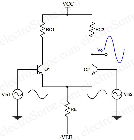
Differential Amplifier Using Transistors
