Transistor Simple Inverter Circuit Diagram
1

Simple Inverter Circuit With Ic556 Timer Chip Electronic Circuit

500w Power Inverter Circuit Using Transistor 2n3055 Inverter
This is a must try inverter for beginners and first time diy inverter makers among hobbyists.
Transistor simple inverter circuit diagram. In the meantime i sing the bolero song in video with. By an inverter circuit. Simple 12v to 220v inverter. Bend the 13007 transistor pins and tin the wires for better soldering.
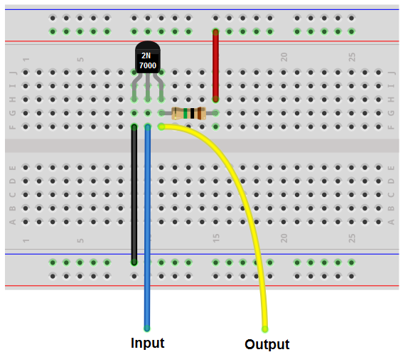
After that current will flow through amplifier up. The output signal voltage is the inverse of the input signal. If you have a single 4060 ic in your electronic junk box along with a transformer and a few power transistors you are probably all set to create your simple power inverter circuit using these components. Now connect 330 ohm resistor as shown in the figure.
Hmi already made this circuit inverter and i read some questions that need help. Simple inverter circuit using ic 555. As above we have to convert 12v battery to 220v ac 50hz. Simple inverter circuit diagram pdf.
I ran the test. Use a 12v battery to directly run the fluorescent bulb. Connection and testing for simple inverter. When apply 12 volts battery to the 50hz frequency generator on square waveform.
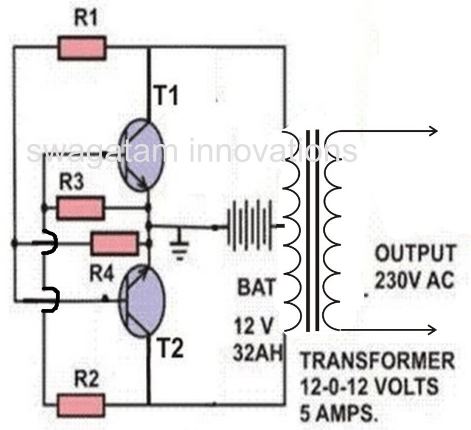
We can make a very reliable inverter using ic 555 and mosfets. In this video we ar going to show how to make a inverter. The transistors in the above circuit holds the most significant part in the working of this circuit where it was wired as a multivibrator. Inverter circuit using transistor.
Connect the t1 t2 transistors emitter together for the 12v inverter circuit. Which we can draw the simple block diagram as figure 4. This video we are used 2n3055 transistorthis transistor is pnp transistor and you can use it as a 12v to. When the input is low 0v the output is high vs.
Ic 555 timer is an ever green integrated circuit which has tons and tons of applications. The basic design of the proposed ic 4060 based inverter circuit can be visualized in the above diagram. When the input is high vs the output is low 0v. This is a small inveter circuit.
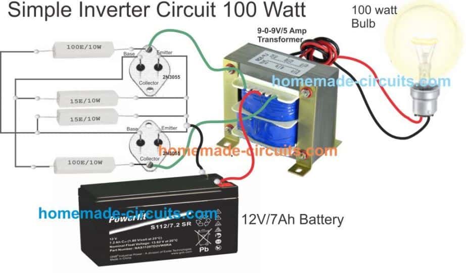
Simple 100w inverter circuit diagram. In the circuit diagram we can observe that 12v battery is connecter to the diode led and also connected to the pin8 of the ic 4047 which is vcc or power supply pin and also to pin 4 and 5 which are astable and complement astable of the ic. 12v to 230v inverter circuit diagram.
Go Look Importantbook Maria Prefer Makes Energy Savings And

7 Simple Inverter Circuits You Can Build At Home Homemade

How To Make A Simple Inverter Circuit Using Transistor 12v Dc To
How To Build An Inverter With A Transistor

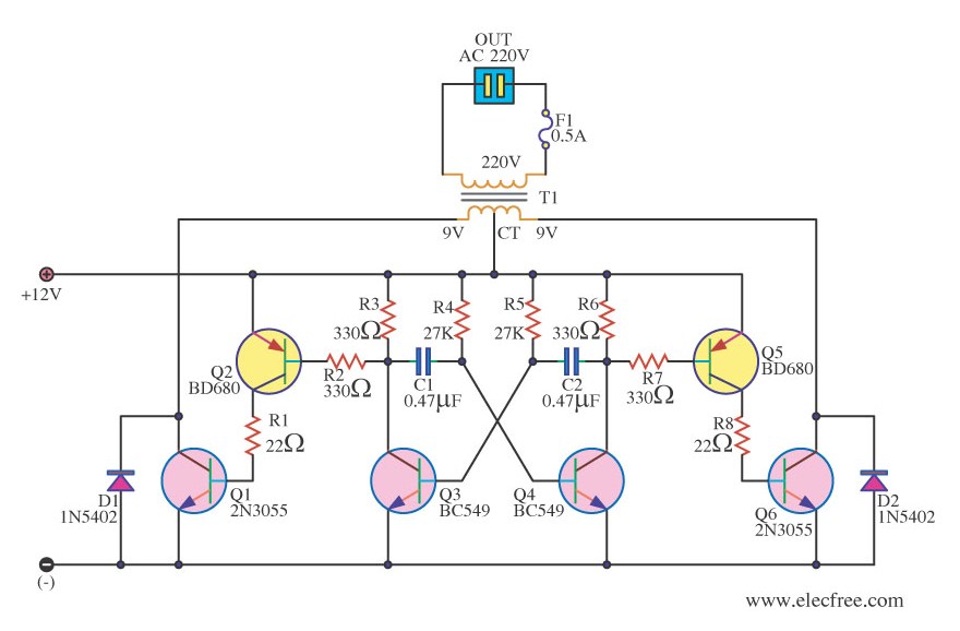
Simple 100w Inverter Circuit 12vdc To 220ac Inverter Circuit And

Simple Inverter Circuit 8 Steps Instructables
Simple 12v To 220v 180w Inverter Circuit Diagram Using 2n3055

1 5v Dc To 220v Ac Converter Envirementalb Com

How To Make Inverter Unlimited Watt 2n3055 Transistor
