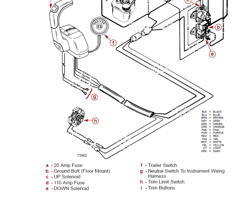
Trim Limit Switch Wiring Diagram
Https Www Telematic Com Documentation Document Dk3y P Pub109 013 00 0415 Pdf
Limit Switch Wikipedia
Https Seatronic No Productattachments Index Download Id 568
The wiring should be at the back of the engine near the transom.

Trim limit switch wiring diagram. Does the electric trim and tilt pump motor not. Meter should show continuity with drive unit in down position. Replace the trim limit and trim sender switchs. Order 9032 screws.
The trim sender wiring and the trim limit wiring that comes from the senders looks alike but the connectors are slightly different. Purchase your trim limit and trim position sender switch kits here. How to clean and possibly fix the existing trim limit switch. The limit switch has 2 male connectors and the trim sender has 1 male 1 female.
Connect an ohmmeter to the switch bullet leads. Testing troubleshooting wiring and bypassing spdt power trim tilt relay harness. With such an illustrative guide you will have the ability to troubleshoot avoid and full your projects with ease. Order 3990 insulator.
Mercruiser power trim limit switch wiring diagram mercruiser trimsender limit switches wiring diagram diy mercruiser alphabravo trim sender install youtube troubleshooting teleflex engine trim gauges mercruiser trim pump troubleshooting help the hull mercruiser 43l efi gen tbi gm 262 v 6 wiring harness mercruiser trim sender. Trim gauge trim senders wiring diagram the wires that connect to the trim pump are for the trim limit switch the sender wire for the guage connects to the sender on the gimbal ring stbd side port side is the trim limit switch. Disconnect the trim limit switch bullet leads from the trim control harness inside the boat see figure 1or figure 3. The trim limit switch is a safety device which keeps the driver from over trimming while under way.
Trim limit switch testing 1. Operate power trim and note meter reading. If the distance is approx. Go to the trimtilt pump assembly and make sure the purple wire connector single wire and the blue wire connector two blue wires on one side of the connection are not corroded or loose.
22 14 inches then the trim limit switch is adjusted properly and the commander trim toggle switch is working in the updown mode. At about one third trim travel the. Your trailer up switch will raise the drive ok but the trim switch does not work. Does not apply to older single pole single throw spst relays.
Mercruiser trim sender wiring diagram you will want an extensive professional and easy to know wiring diagram. This is quicksilver pn 85 63990 side insulator. Your trim gauge does not work.

Circuit To Reverse Polarity Electrical Engineering Stack Exchange

My 5706 Johnson Outboard Tilt Trim Wiring Diagram Free Diagram
Http Cdn Jamisondoor Com Drawings Cad J Series J9000 J9040 9049 J9044 J9044038 Pdf
1591612488000000
Husaberg Motorcycles Manual Pdf Wiring Diagram Fault Codes

Mercruiser Trim Sender Kit Michigan Motorz
How To Repair A Mercruiser Alpha One Trim Limit Switch Before
Trim Tilt Wiring Question Again

Trim Limit Switches Wiring Page 1 Iboats Boating Forums 598392
