Truth Table Logic Circuit Diagram

Electronics Done Quick 7 Logic Ga Robotshop Community

Converting Truth Tables Into Boolean Expressions Boolean Algebra

Wd 3672 Basic Logic Gates Digital Circuits Worksheets Free Diagram
Truth table karnaugh map minimal form gate.
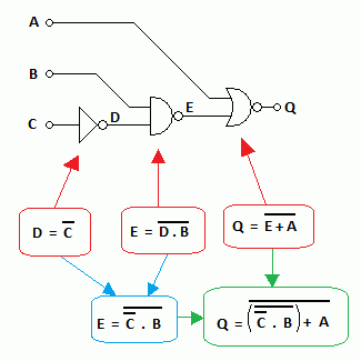
Truth table logic circuit diagram. Give the boolean expression from the above circuit diagram. Drawing of k map for each output. This means that these truth tables can be used to deduce the logical expression for the given digital circuit. The logic diagram representation is shown below.
A truth table has the same states as in number 3 above. How to create a logic circuit truth table creating a truth table for a logic circuit is trickier than doing so for a single gate. Code converters binary to excess 3 binary to gray and gray to binary. The full adder fa circuit has three inputs.
Not gate or an inverter. A b and cin which add three input binary digits and generate two binary outputs ie. Priority encoders encoders and decoders simple explanation designing. Multiplexer and demultiplexer the ultimate guide.
Sr flip flop is the simplest type of flip flops. Determing the truth table and logic statement. Truth tables list the output of a particular digital logic circuit for all the possible combinations of its inputs. From this truth table the k maps are drawing shown in figure 1 to obtain a minimized expression for each output.
4 bit parallel adder and 4 bit parallel subtractor designing logic diagram. Titlefull adder truth table logic diagram class. Logic gates truth tables boolean algebra and or not nand nor duration. Logic gate questions are a great way to test your knowledge on the topic of truth tables.
Binary to bcd code code converter. An adder is a digital logic circuit in electronics that performs the operation of additions of two number. Half adder and full adder. The organic chemistry tutor 382156 views.
Adders are classified into two types. Explain half adder and full adder with truth table an adder is a digital logic circuit in electronics that implements addition of numbers. Sr flip flop construction logic circuit diagram logic symbol truth table characteristic equation excitation table are discussed. Logic circuits are designed to perform a particular function understanding the nature of that function requires a logic circuit truth table.
Complete the truth table and convert the output column to hexadecimal if the state 0 is the least significant bit and the state 7 is the most significant bit.

Free Truth Table To Logic Circuit Converter Software For Windows
Digital Electronics Logic Gates Basics Tutorial Circuit Symbols

Basic Logic Gates Using Discrete Components
Truth Table With Logical Gates For A Traffic Light Electrical
What Is A Logic Gate A Beginner S Guide

Ecen 1400 Intro To Digital Analog Electronics Spring 2014 Lab 6
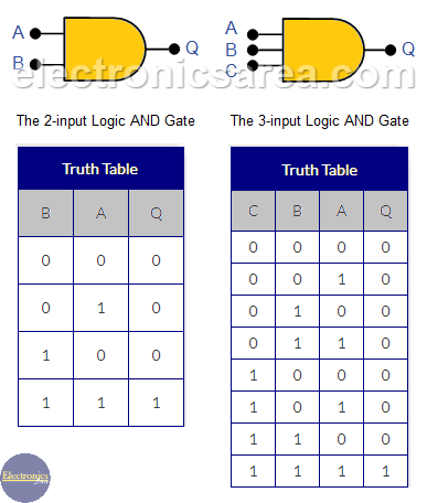
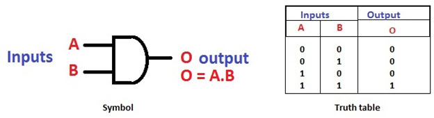
Logic And Gate Tutorial 2 3 Input And Gate Truth Table

Logic Gates In Details Name Graphic Symbol Algebraic Function
Basic Logic Gates With Truth Tables Digital Circuits
