Two Bit 2 Bit Comparator Logic Diagram
The truth table for a 4 bit comparator would have 44 256 rows.

Two bit 2 bit comparator logic diagram. 22 logic diagram according to logic function obtained from truth table logic diagram is drawn as in fig2. Please try again later. Comparator is most fundamental component that performs comparison operation. We will compare each bit of the two 4 bit numbers and based on that comparison and the weight of their positions we will draft a truth table.
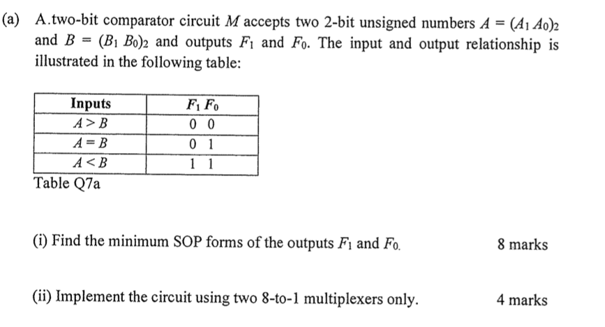
The truth table for a 2 bit comparator is given below. It consists of one nmos one pmos. Using cmos logic style fig3 a represents symbol of cmos inverter. 2 bit magnitude comparator design using different logic styles 31.
This brief presents comparison between different logic styles used to design 2 bit magnitude. It consists of four inputs and three outputs to generate less than equal to and greater than between two binary numbers. Comparison is most basic arithmetic operation that determines if one number is greater than equal to or less than the other number. 2 bit magnitude comparator a comparator used to compare two binary numbers each of two bits is called a 2 bit magnitude comparator.
2 bit magnitude comparator design using different logic styles is proposed in this brief. So we will do things a bit differently here. Working principle of 2 bit comparator circuit with truth table logic diagram. This feature is not available right now.
A 2 bit comparator compares two binary numbers each of two bits and produces their relation such as one number is equal or greater than or less than the other. The figure below shows the block diagram of a two bit comparator which has four inputs and three outputs.