Voltmeter Schematic Diagram

Mosfet Wiring Diagram Field Effect Transistor Voltmeter Led
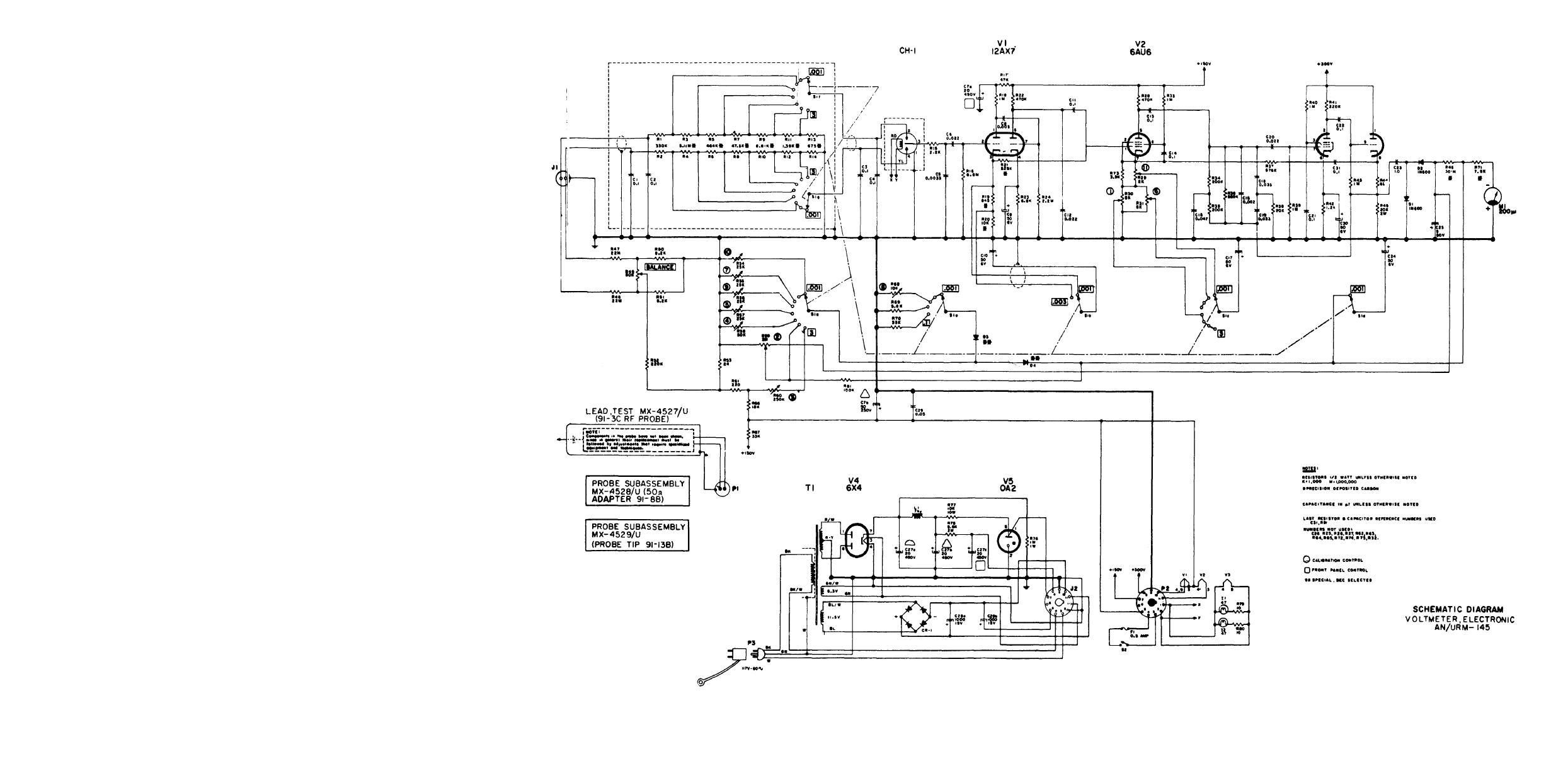
Schematic Diagram Voltmeter Electronic An Urm 145

A Schematic Diagram Of The Functional Seasoning Setup For Leds
At that time i used a large circuit.
Voltmeter schematic diagram. Question 1 suppose i were about to measure an unknown voltage with a manual range voltmeter. Lets build an icl7107 digital voltmeter circuit. This particular voltmeter has several different voltage measurement ranges to choose from. It is an important basis for other measurement tools circuits.
When the input voltage is too high the display goes out. Now building a digital voltmeter circuit does not need high technology and big circuit. The schematic diagram of this project. Draw the schematic diagram for the circuit to be analyzed.
Rf voltmeter schematic diagram data manual pdf voltmeter ammeter lcd panel electronics lab pdf dsn vc288 dual digital voltmeter circuit schematic ammeter volt current meter datasheet 4 100v 10a pdf. Digital led voltmeter circuit diagram next apply a known voltage to the input and adjust p2 till the leds read the correct value. When the input is negative the unit leds do not light. Digital dc voltmeter circuit.
Some people may find it helpful to use a different colour for each of the three groups of leds. Introduction electrical parameters like voltage and current are inherently associated with electronics and with electronic engineers. Icl7107 is a 35 digit analog to digital converter adc which consumes very low power. When being a teenager.
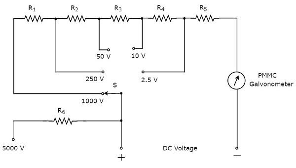
Voltmeter design dc electric circuits pdf version. Some darsonval movements have full scale deflection current ratings as little as 50 ua with an internal wire resistance of less than 1000 w. Powerline voltmeter schematic circuit diagram. 500 volts 250 volts 100 volts.
In this article we learn how to build a digital voltmeter and a digital ammeter combined circuit module for measuring dc volts and current through different ranges digitally. Ive built this circuit. In this project we are going to build a digital voltmeter without using any microcontrollerhere we are using a very popular ic for voltage measurement namely icl7107cs7107using icl7107 we can build accurate and very low cost voltmeter. Powerline voltmeter schematic circuit diagram.
This makes for a voltmeter with a full scale rating of only 50 millivolts 50 ua x. October 02 2018 in. Of course the easiest way is used as the dc voltage meter circuit. Power supplies no comments.
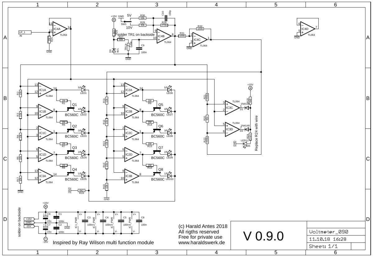
Www Haraldswerk De Next Generation Formant Voltmeter
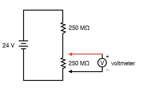
Voltmeter Impact On Measured Circuit Dc Metering Circuits
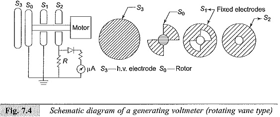
Generating Voltmeter Principle And Construction Advantages
Multimeter Tutorialspoint

Digital Voltmeter Circuit Diagrams Schematics Electronic Projects
Voltmeter Diagram Symbol
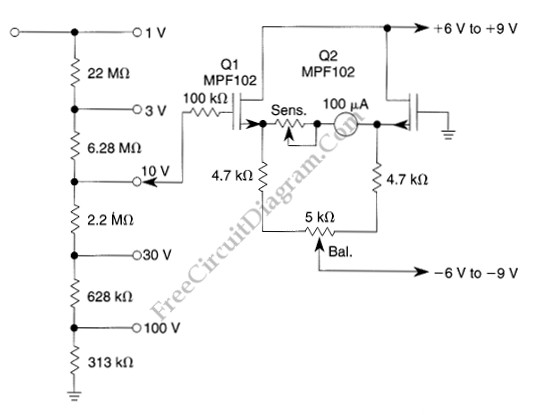
The Low Drift High Impedance Jfet Dc Voltmeter Basic Circuit

Rc 2626 Range Meter Circuit Schematic Wiring

Lessons In Electric Circuits Volume Vi Experiments Chapter 3
