Vss 3 Wire Speed Sensor Diagram
Tachometer And Speedometer
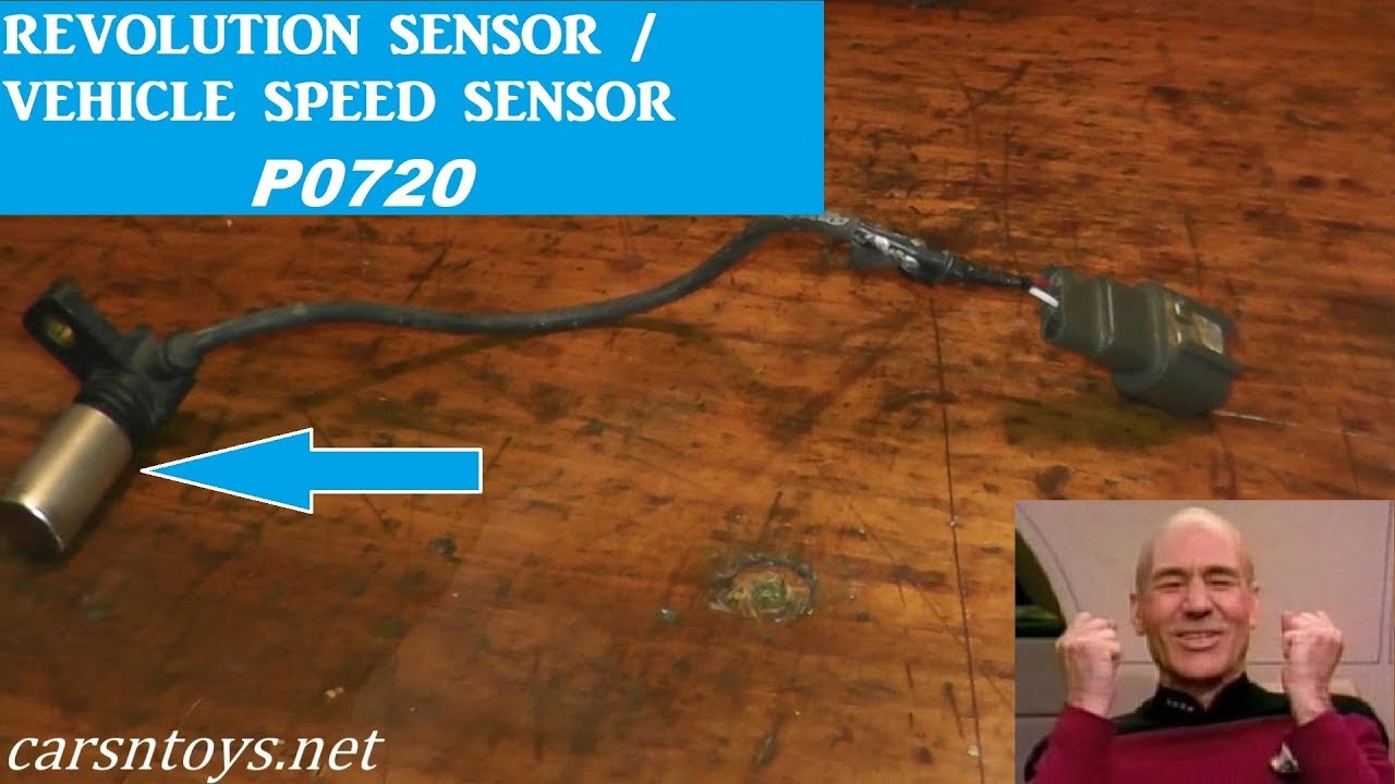
Revolution Sensor P0720 Testing And Replacement Youtube
Https Documents Holley Com Techlibrary 199r10555rev16 Pdf
The three wire sensor part no.
Vss 3 wire speed sensor diagram. Vehicle speed sensor testing. A vehicle speed sensor or vss is a sensor that is used to determine how fast your vehicle is traveling. If the resistance is 190250 ohms the sensor is okay. They can come in all different technologies such as inductive photoelectric and capacitive just to list a fewalthough the sensor technology may differ all 3 wire sensors are wired the samea three wire sensor has 3 wires present.
Using a digital volt ohmmeter dvom measure the resistance ohmmeter function between the sensor terminals. Vehicle speed sensor faulty failing symptoms malfunction p0500 duration. Spinning the hub there is no change in the sensor voltage. Vehicle speed sensor replacement.
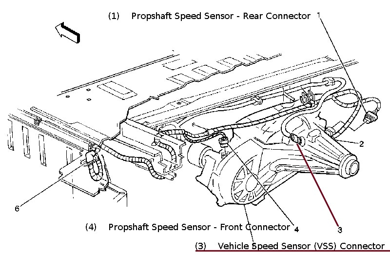
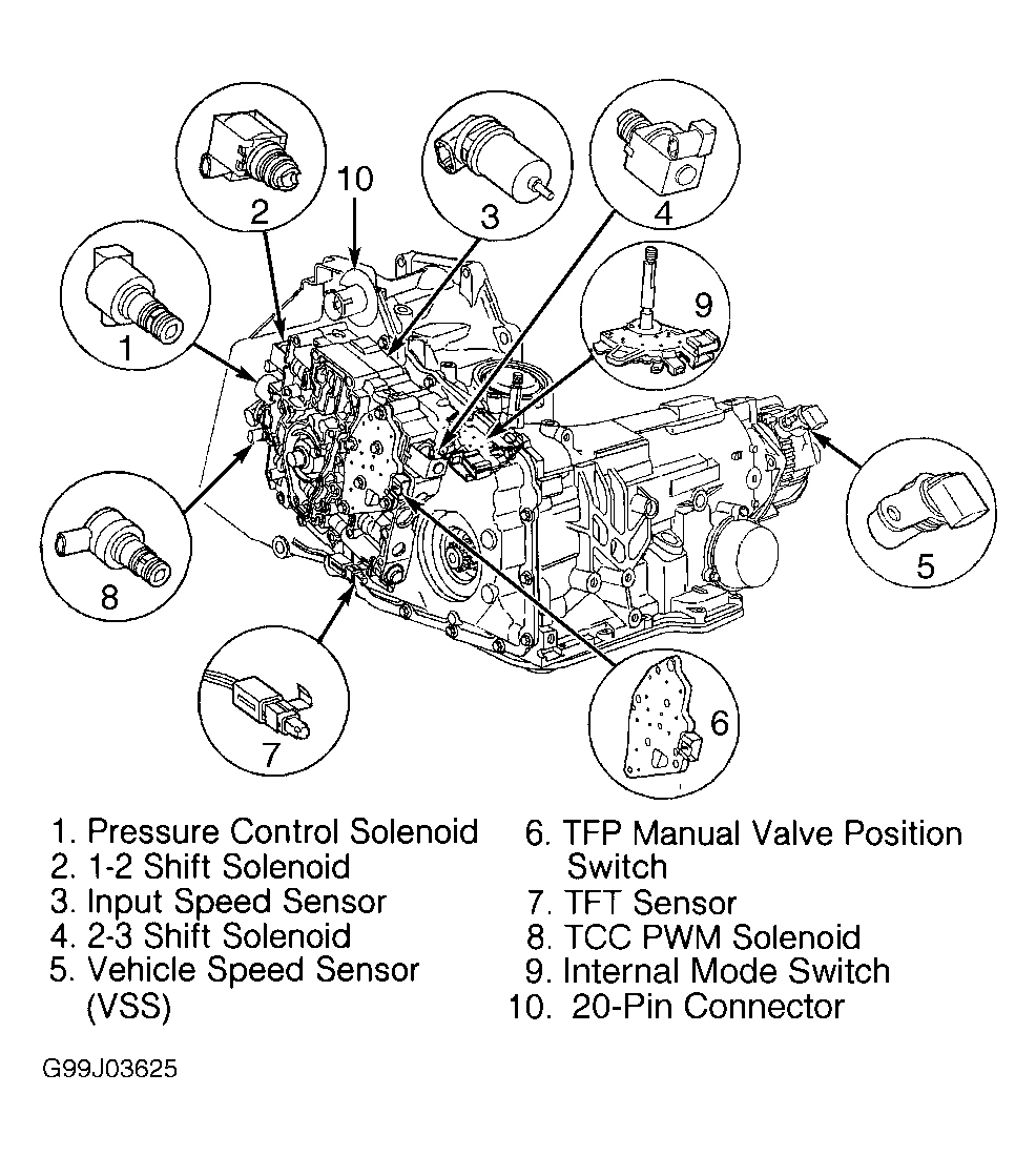
The sensor read open on all three wires or millions of ohms. How to test a 3 wire speed sensor autometer products inc. Top 5 auto repairs 26124 views. There must be a speed sensor usually a two wire.
How to test a 3 wire speed. Three wire sensors are used in various applications from detecting parts to locating position of the actual machine. If your vehicles speedometer stops working or isnt telling you the correct speed that youre traveling you likely have a faulty vss. Turn the ignition switch to the off position.
One wire is positive one negative and one is the sensor wire. Testing for a speedometer signal download pdf. Disengage the wiring harness connector from the vss. Basic sensor testing wiring diagram.
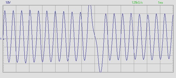
Speed sensor wiring diagram for a 2001 ford f350 with a 73 l power stroke diesel vss wire i admit i hate to fight my way look at the wiring diagram for the instrument cluster. Sn16 works by switching pulsing a reference voltage on and off as the sensor spins. When on i get 8 volts from positive to ground and 375 volts from sensor to ground with the sensor plugged into the speedometer head. Testing vehicle speed sensor vss output speed sensor oss transmission speed sensor tss duration.
First off is testing the 2 wire speed sensor. The 3 wire speed sensor is externally powered so you will need a power source of some form.
Https Documents Holley Com Techlibrary 199r10555rev16 Pdf

Digital Gate An Overview Sciencedirect Topics
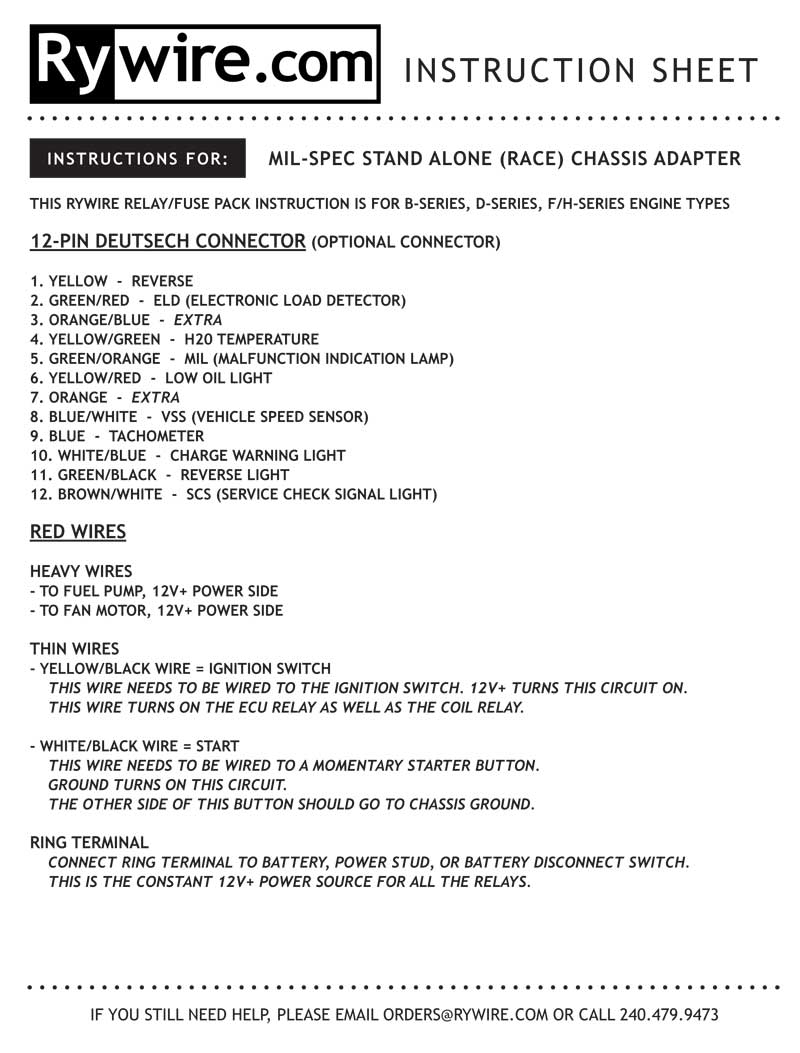
Instruction Sheet
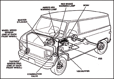
Kelsey Hayes 4wal Antilock Brakes

144 Questions With Answers In Inductor Science Topic
Https Documents Holley Com Techlibrary 199r10555rev16 Pdf
Wrg 9159 2000 Pontiac Grand Prix Fuse Diagram

Reed Switch Wikipedia

Bmw E90 Abs Sensor Replacement E91 E92 E93 Pelican Parts Diy
