Wire Outlets In Parallel Diagram

Electrical Breaker Wiring Diagram Diagram Base Website Wiring
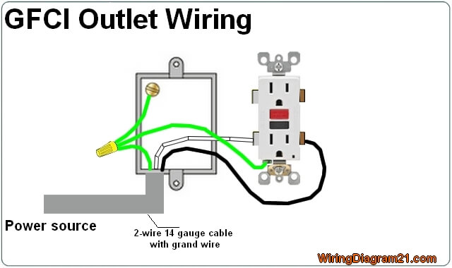
Siemens Gfci Wiring Diagram Diagram Base Website Wiring Diagram

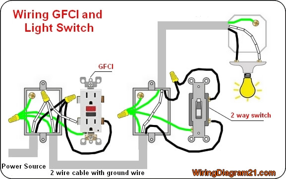
Wiring Diagram For Switch And Outlet Diagram Base Website And
This is the outlet wiring diagram parallel how to wire multiple outlets and of a image i get coming from the wiring lights in parallel diagram collection.

Wire outlets in parallel diagram. Parallel or in series or daisy chained and the difference between the two. Starving electrician 22812 views. Here we compare wiring an electrical receptacle in series or daisy chained the most common practice with wiring receptacles in parallel on an electrical circuit. How to wire plugs how does wiring them affect the electrical circuit duration.
How to with sam. How to wire multiple outlet in parallel electrical wiring diagram. Pigtail the ground wire from the romex with a length of ground wire connected to the green screw. Turn the power back on to the circuit and check each outlet for power.
Wire plugs series or parallel. Sep 28 2018 how to wire multiple outlet in parallel electrical wiring diagram. You can save this photographic file to your individual computer. Keep in mind that series connection of outlet is against the nec code also it doesnt make sense as if one of the outlet wires cuts or one faulty outlet will make the whole circuit useless except gfci and afci receptacles.
Here 3 wire cable is run from a double pole circuit breaker providing an independent 120 volts to two sets of multiple outlets. Wiring diagram for dual outlets. If you are fixing more than one outlet the wiring can be done in parallel or in series. Check each of your connections again but dont affix the outlets to the wall just yet.
How to wire up an electrical receptacle in one of two methods. Please right click on the image and save the graphic. Basic electrical wiring electrical wiring diagram electrical outlets garage design fence design 3 way switch wiring popup camper remodel barn shop house wiring. A parallel circuit is also a closed circuit where the current divides into two or more paths before coming back together to complete the full circuit.
With the last outlet the circuit is wired in parallel. Each outlet is independent of each others as they are wired to separate cables. This wiring is commonly used in a 20 amp kitchen circuit where two appliance feeds are needed such as for a refrigerator and a microwave in the same location. The neutral wire from the circuit is shared by both sets.
In this simple wiring diagram multiple outlets have been connected in parallel. Much more common than series circuits are those wired in parallelincluding most household branch circuits powering light fixtures outlets and appliances.

92f92w Diagram Schematic Smart Plug Wiring Diagram Full Hd Quality

Smart Light Switch Wiring Diagrams Mr Electrician
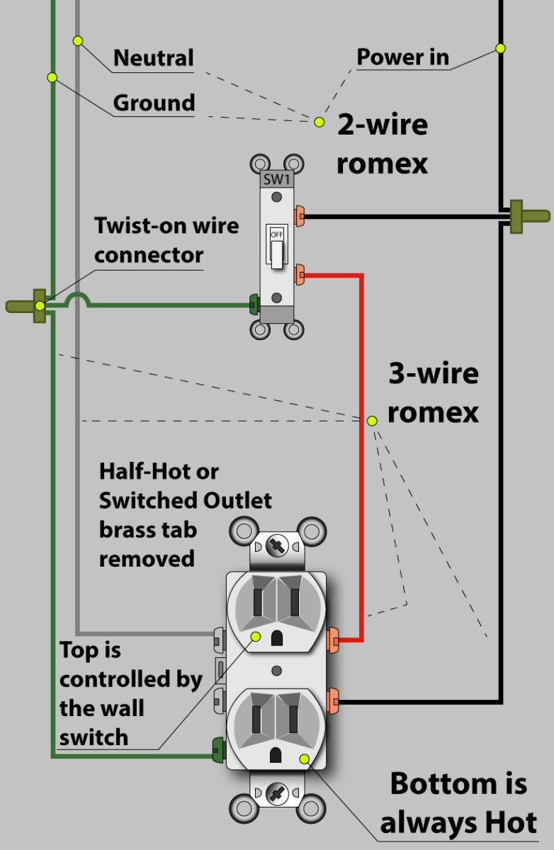
Wiring Outlet With A Switch For Garbage Disposal Home
Siemens Gfci Wiring Diagram Diagram Base Website Wiring Diagram
Wiring Diagrams For Multiple Receptacle Outlets Do It Yourself

Smart Light Switch Wiring Diagrams Mr Electrician
How To Wire An Outlet Receptacle Socket Outlet Wiring Diagrams

How To Wire Multiple Outlet In Parallel Electrical Wiring Diagram

Light And Switch Wiring Multiple Receptacles Diagram Diagram Base
