Wiring Diagram Fan Speed Controller
Wiring Diagrams For A Ceiling Fan And Light Kit Do It Yourself

A39 Wiring Diagram For Fireplace Fan Wiring Resources

How To Wire 3 Speed Fan Switch
32e500f series fan speed controller installation instructions.
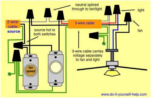
Wiring diagram fan speed controller. In the below ceiling fan speed control switch diagram i shown the fan speed switch knob on off direction. So yellow for 15 uf and purple for 25 uf. The source is at the switches and the input of each is spliced to the black source wire with a wire nut. So here is an complete diagram in which is shown the ceiling fan motor main winding and auxiliary winding starting winding with speed controller switch capacitor and ac supply.
This is actually a fairly simply switch that is mounted on the wall. Fan speed controller circuit car fan speed controller circuit operation. This one is a schurz. The output of the multivibrator is fed to irf 540 mosfet.
Free wheeling diode d1 protects the motor from back emf. This wiring diagram illustrates the connections for a ceiling fan and light with two switches a speed controller for the fan and a dimmer for the lights. The slow speed is obtained by using the 43uf capacitor purple p the medium speed is obtained by using the 21uf capacitor red r and the high speed is. Heres some similar controllers.
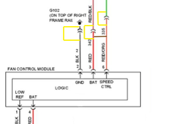
Fan control wiring is not polarity sensitive. 90 wiring diagrams 91 one way operation 92 two way operation. A fan speed control switch makes it easy to adjust the speed at which a fan spins. Filmed this while filming my last vlog and wanted to do a dedicated diy on how to wire an electronic fan controller.
Capacitor c1 is connected in parallel to the fan to stabilize its speed. Is there a wiring diagram for the 40csfm 3 speed fan controller. The clipsal 2031vf3c and 31vf3c series ceiling sweep. 06 december 2019 there is a wiring diagram available.
Note the crude circuit diagram on the black box object the fan speed controller i infer that the fan controller works by inserting a capacitance into the fans power supply circuit. How to install a ceiling fan speed control is quite easy but you still need to pass or to have a 3 wire cable installed 143. The fan is connected to the positive terminal of the battery and drain d of mosfet t1. The fan speed controller is switched on or off using the 30 series switch mechanism provided.
2031vf3c and 31vf3c series fan speed controls are connected as illustrated in the diagram below. 3 speed controller for airflow ceiling sweep fans wiring and installation instructions f996 9922 check list included.

Wrg 1907 Load Control Switch Wiring Diagram
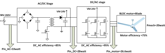
Designing An Energy Efficient Bldc Ceiling Fan Solution
C6 Z06 Cooling Fan Wiring Diagram Corvetteforum Chevrolet

Four Wire Fan Diagram Wiring Diagram
Ceiling Fan Wiring Diagram
Best Options For Ceiling Fan Wall Switch W 2 Wire Cabling The

Wiring Solid State Fan Controller Electrical Diy Chatroom Home
Cooling Components Fan Wiring Diagram Diagram Base Website Wiring
How To Use Esp8266 Esp 12f Or Arduino To Control Ebmpapst 48v Dc Fan
