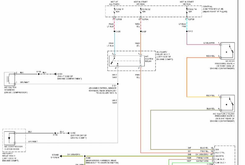
Wiring Diagram For A C Compressor
The simplest approach to read a home wiring diagram is to begin at the source or the major power supply.

Wiring diagram for a c compressor. Consult the wiring diagram for the model locating the green wire that is coming from the throttle area. The wiring diagram identifies the fan motor and compressors wire colors and functions. It reveals the elements of the circuit as simplified shapes as well as the power and signal connections in between the tools. C neutral wire will be connected to fan motor and compressor without goes through any switch.
A wiring diagram is a streamlined standard photographic representation of an electric circuit. Sometimes wiring diagram may also refer to the architectural wiring program. These connections are made on the wire connector in the back of the selector switch so all neutral wires are common to each other because they are connected to the same point. David talks about basic compressor wiring.
The letters stamped into the compressors housing near the wire terminals identify each terminal function. A wiring chart on the fan motors case also identifies the fan motors wire colors and each wires function. Most models use a green wire for this connection as it has become an industry standard. Diagram 2000 chevy s10 a c compressor wiring diagram full 2000 s10 ac relay amazing wiring diagram product 2003 s10 fuse panel diagram wiring diagram rows diagram trailer wiring diagram for 2001 chevy 1500 full gm ac wiring diagram wiring diagram 1989.
Variety of ac compressor wiring diagram. Typically a solenoid attached to the throttle is activated when the system is turned on and the lead from this component will power the compressor clutch. The wiring diagram on the opposite hand is particularly beneficial to an outside electrician.