Wiring Diagram For Electric Brake

Trailer Wiring Guide
76b9051 Brake Force Brake Controller Wiring Diagram Wiring Resources

Ay 4905 Trailer Wiring Diagram Brake Away Schematic Wiring
Electric trailer jack wiring diagram download.

Wiring diagram for electric brake. Technical assistance call toll free. A circuit is usually composed by many components. Even with a standard minimum of 16 gauge cables used in some trailer circuits elecbrakes functions correctly. The white wire must be connected to a known ground.
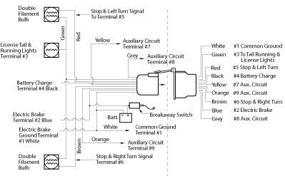
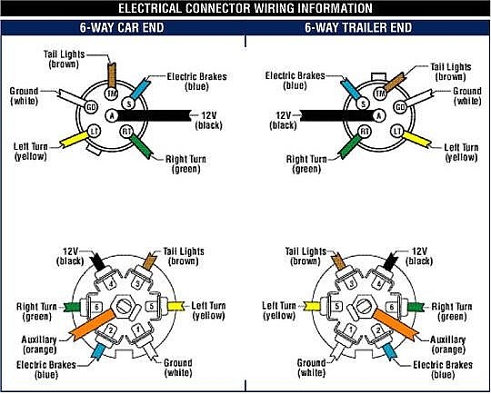
Blue electric brakes or hydraulic reverse disable see blue wire notes below in the trailer wiring diagram and connector application chart below use the first 5 pins and ignore the rest. There are two things which are going to be present in almost any 7 pin trailer wiring diagram with brakes. Components of 7 pin trailer wiring diagram with brakes and some tips. This universal wiring kit lets you install an electric brake controller sold separately in your vehicle and a 7 way connector for your trailer lights at the same time.
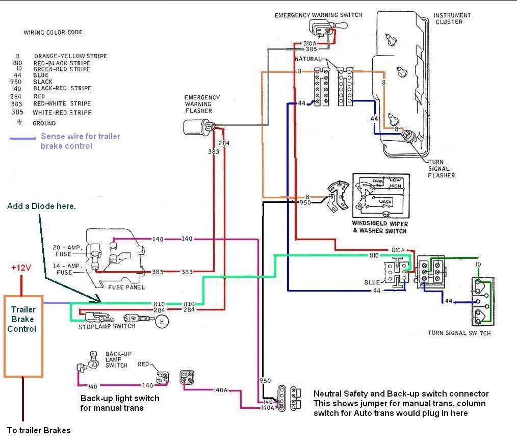
There are wires extending from the switch and using a circuit tester you can find the wire that has power when the brake pedal is pressed. By law trailer lighting must be connected into the tow vehicles wiring system to provide trailer running lights turn signals and brake lights. Black wire positive battery white wire negative battery red wire cold side of stoplight switch blue wire brake output to trailer 1. When comparing wire thickness a smaller gauge number represents a thicker wire.
Click on the image to enlarge and then save it to your computer by right clicking on the image. The first component is symbol that indicate electrical element from the circuit. It reveals the components of the circuit as streamlined shapes and also the power as well as signal links in between the tools. Brake switch red this is usually found near the top of the brake pedal.
Wiring diagram for stock trailer refrence lovely trailer wiring. This is accomplished by tapping into the tow vehicles electrical harness to transfer power to the trailer wiring system. Electric brake controller wiring diagram wiring diagram auxiliary connection is optional it may be connected to any 12v to 24v constant power source or left unconnected. Collection of electric trailer brake wiring schematic.
There is a range of wire sizes available for trailer circuits and electric brake wiring. If your truck has a built in 7 pin socket but you only need 5 of the pins. Breakers protect your vehicles electrical system by preventing overload quick splice wiring connector lets you easily connect your brake controllers stop signal wire to your brake pedal.
Electric Trailer Brake Wiring Diagram
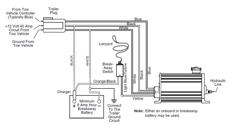
Dexter Dx Series Electric Over Hydraulic Brake Actuator For Drum

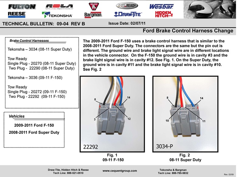
I Have A 96 Ford F 150 Trying To Wire Up The Trailer Plug For

Diagram Of A Brake Controller Intallation With Images Tekonsha
Glow Plug Controller Wiring Harness Diagram Base Website Wiring
How To Wire Up Electric Trailer Brakes

Wiring Trailer Lights And Brakes Nest Light Bulbs Wiring Diagram

Redline Brake Controller Wiring Diagram

Horse Trailer Electrical Wiring Diagrams Lookpdf Com Result
