Wiring Diagram For Electric Brakes

Master Tow Dolly Wiring Diagrams Trailer Electric Cars Electricity

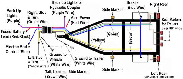
Trailer Wiring Diagram Lights Brakes Routing Wires Connectors
Trailer Axle Electric Brake Wiring Diagrams Diagram Base Website
Electric over hydraulic brake actuator activates your trailers hydraulic brakes when you apply the brakes in your vehicle brake controller sold separately is required to send signal.
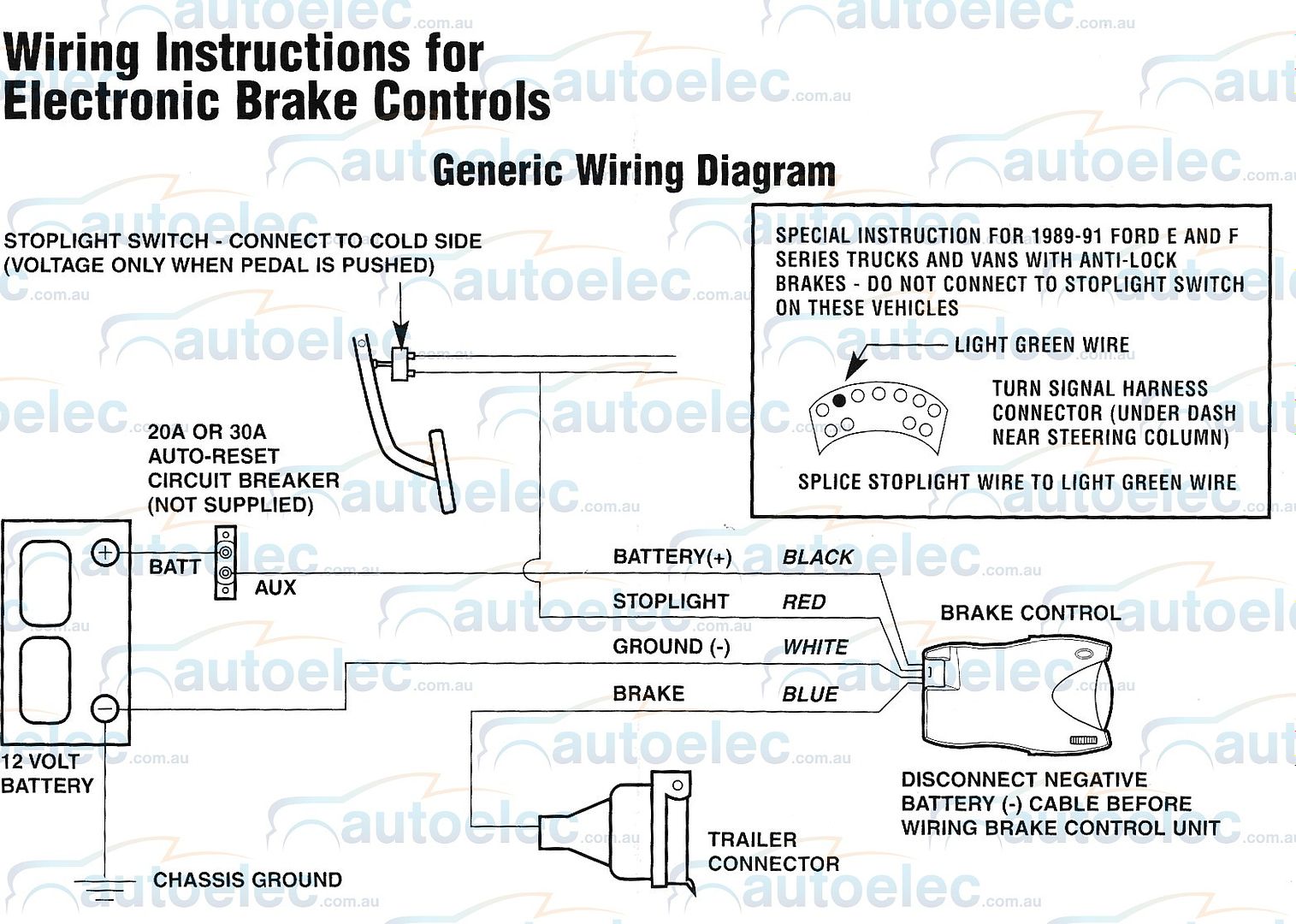
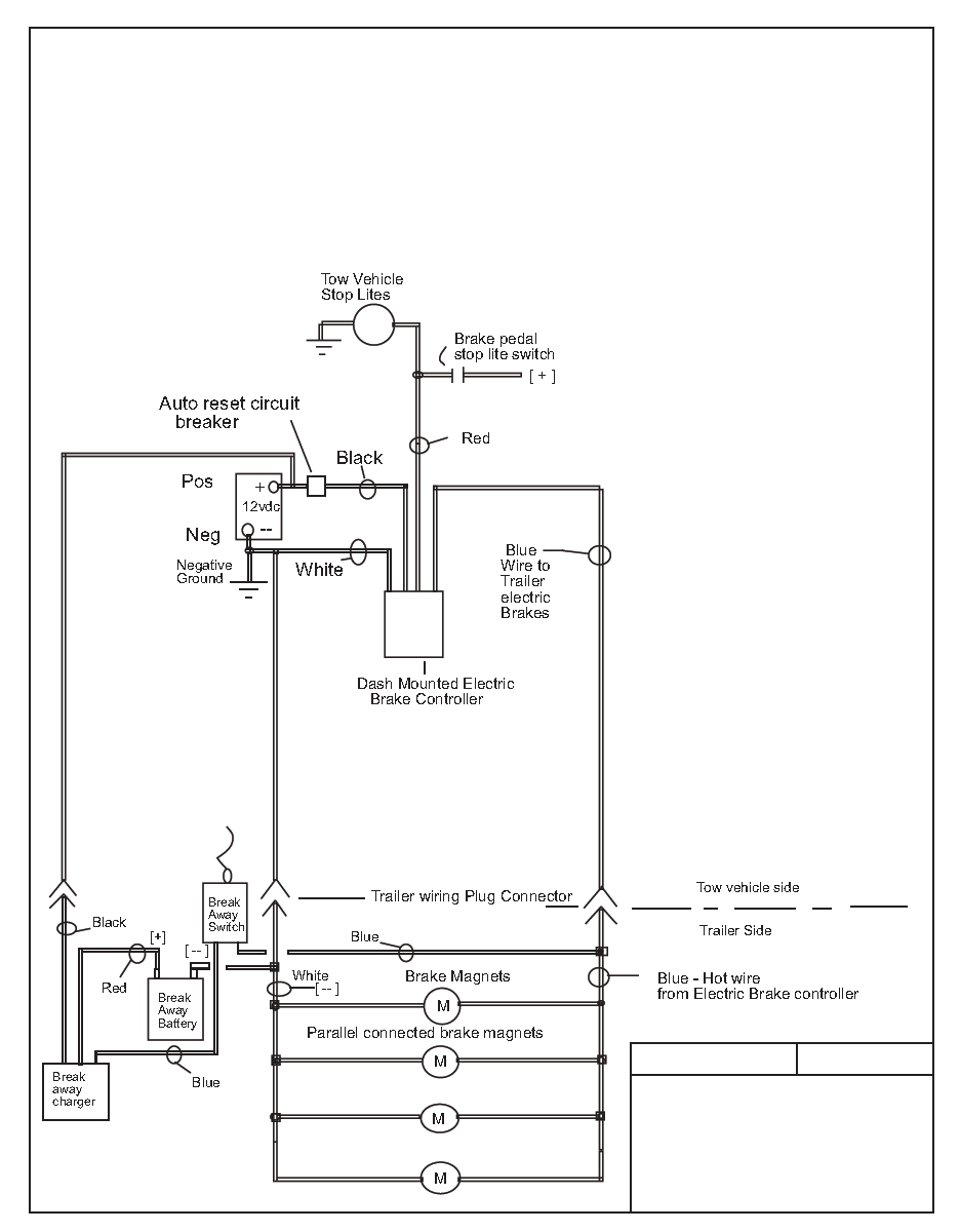
Wiring diagram for electric brakes. A wiring diagram is a simplified traditional pictorial representation of an electrical circuit. Each component should be set and connected with different parts in specific way. Whether your connecting a brake controller or wanting to run 15 30 or 50 amps of additional power hayman reeses plug and play smartclick wiring system makes it easier than ever to fit a range. Trailer wiring diagram a brake controller has only one output wire.
Electric trailer brake wiring schematic collections of electric trailer jack wiring diagram download. How electric trailer brakes work. What gauge wire for electric trailer brakes. There is a range of wire sizes available for trailer circuits and electric brake wiring.
Wiring diagram for stock trailer refrence lovely trailer wiring. Electric hydraulic brake actuator works with your brake controller sold separately to activate your trailers disc brakesvented housing releases heat and moisture. The service brake circuit must be disconnected from an existing trailer plug. Collection of trailer wiring diagram with electric brakes.
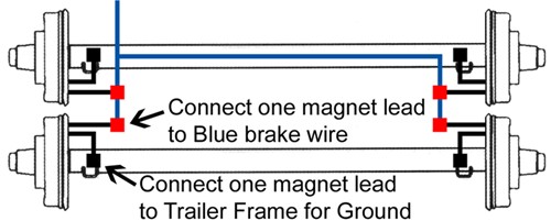
2008 dodge ram 1500 trailer brake wiring diagram fresh dodge wiring. It reveals the components of the circuit as streamlined shapes and also the power as well as signal links in between the tools. How electric trailer brakes work. If that wire runs to one wheel then the other then the other and the other as demonstrated above it creates that twisting feeling under braking.
Elecbrakes must be connected to trailer wiring circuits as outlined in the wiring diagram. Skip navigation sign in. Enhanced wiring protection. Curt trailer brake controller wiring diagram control in wiring.
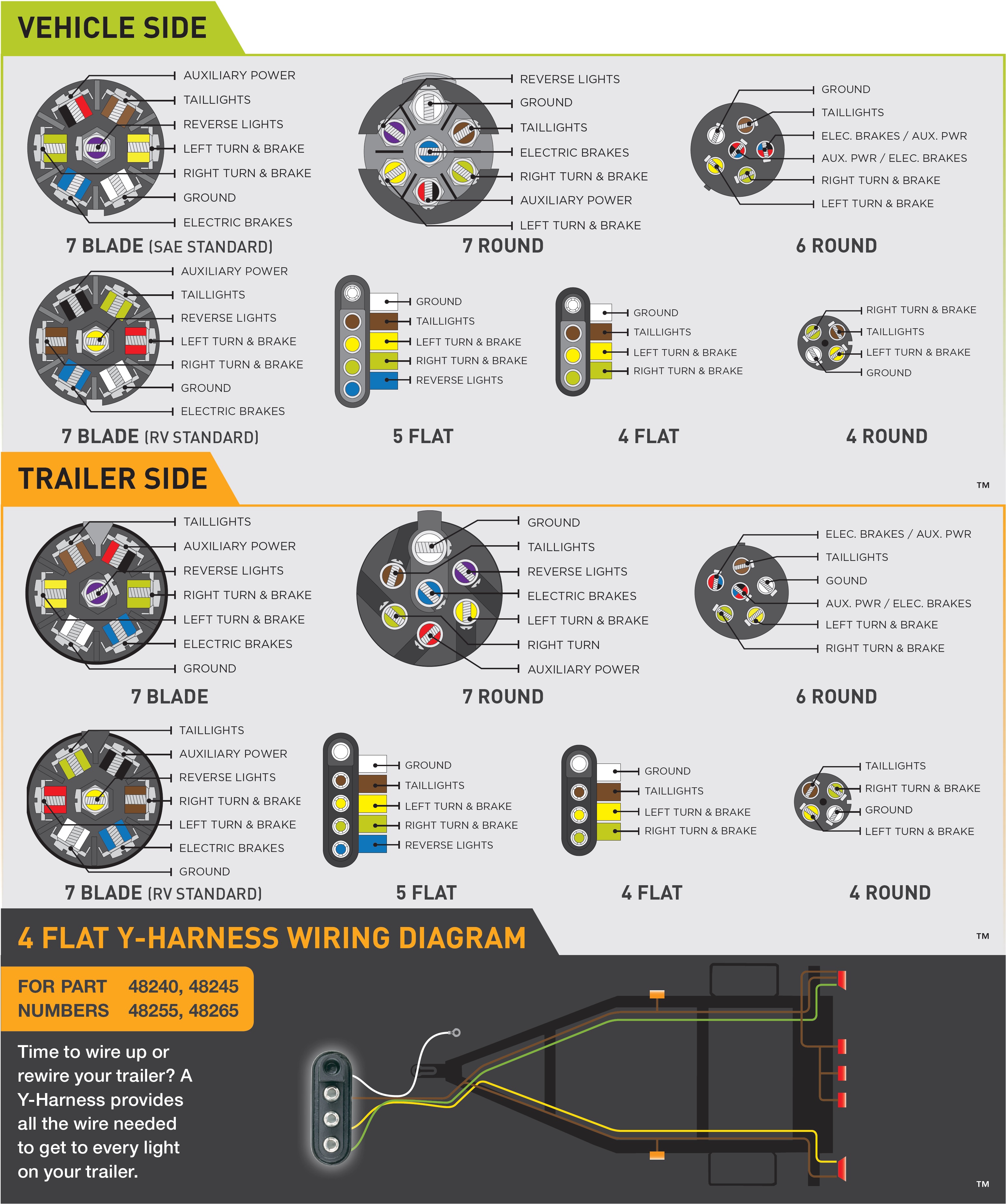
In this case its mandatory that these brakes are electric with a compliant electric brake controller fitted. Ensure it is sealed off and cannot create a short circuit with any other wire or the chassis. Trailer wiring diagram with electric brakes 7 pin trailer wiring diagram with electric brakes 7 way trailer plug wiring diagram with electric brakes trailer light wiring diagram with electric brakes every electric arrangement is composed of various distinct pieces.

Trailer Wiring And Brake Control Wiring For Towing Trailers

Trailer Hitch 7 Pin Wiring Diagram Diagram Base Website Wiring
Chevrolet Trailer Brake Wiring Diagram Diagram Base Website Wiring
Wrg 1669 Wiring 7 Pin Trailer Diagram

Reverse Light Wiring Diagram 7 Way Hitch Diagram Base Website Way
Trailer Wiring Diagrams Etrailer Com

1993 One Ton Gmc Trucks Wiring Oem Supplied Brake Controller
Electric Brake Control Wiring

Image From Http Www Offroaders Com Tech Images 7 Wire Trailer
