Wiring Diagram For Ground Fault Receptacle

Air Conditioner Electrical Circuit Diagrams Wiring Diagram Indoor

31c92 Wiring Diagram For Kitchen Counter Plugs Wiring Library

Duplex Gfci
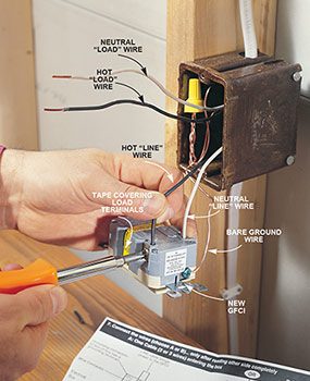
Wiring a ground fault circuit interrupter there are two sets of separated terminals on a ground fault circuit interrupter gfci receptacle.

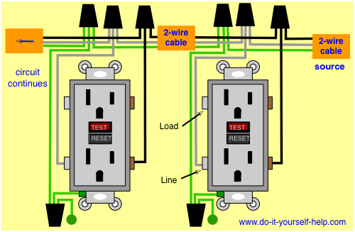
Wiring diagram for ground fault receptacle. This diagram illustrates the wiring for multiple ground fault circuit interrupter receptacles with an unprotected duplex receptacle at the end of the circuit. One side of the gfci connected to the ground neutral wire as shown white in the diagram and another side to the high potential hot wire shown as black in the diagram shows as in black color. How to wire a gfci and receptacle. It reveals the parts of the circuit as simplified forms as well as the power and signal links in between the tools.
The line terminals and the load terminals. Arc fault circuit interrupters afcis replace an electrical outlet. What is a gfci. The source from the circuit should be connected to the line terminals and any standard duplex outlet or other device connected to the load terminals will be protected by this gfci.
Refer to the diagram above about wiring gfci receptacles for additional help. In the diagram below a 2 wire nm cable supplies line voltage from the electrical panel to the first receptacle outlet box. The above diagram shows the gfci wiring to multiple outlet as in white while the pictures are same. If more than 1 black and 1 white conductor are in the electrical box also loosen the load side silver and brass terminal screws.
It shows the components of the circuit as streamlined shapes and the power as well as signal connections in between the devices. I will list below the. A wiring diagram is a streamlined traditional photographic depiction of an electric circuit. In this video i will show you how to wire up a gfi and make a receptacle gfi protected.
The black wire line and white neutral connect to the receptacle terminals and another 2 wire nm that travels to the next receptacle. Loosen the silver and brass terminal screws on the line side of the outlet. Ground fault circuit interrupters gfcis gfci load wiring. Collection of ground fault receptacle wiring diagram.
The load terminals on the gfci are not used and the last receptacle is wired directly to the circuit source. This repeats until the end of the chain. Variety of leviton gfci receptacle wiring diagram.
%2BOutlet%2BWiring%2BDiagram.jpg)
Electrical Engineering World Ground Fault Circuit Interrupter

Wiring A Gfci Outlet How To Wire Line And Load Schematics
Wiring Diagrams For Electrical Receptacle Outlets Do It Yourself

How To Wire Switches

Ft 9556 Ground Fault Circuit Interrupter Wiring Diagrams

C4eb8 Ground Fault Indicator Light Wiring Diagram Wiring Library

How To Install Electrical Outlets In The Kitchen Step By Step
Wrg 3427 Wiring Diagram Hot Wire White Bathroom
How To Install Gfci Receptacle Outlets The Family Handyman
