Wiring Diagram For Receptacle

Switched Outlet Wiring Diagrams Mr Electrician
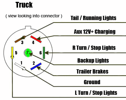
7 Way Diagram Aj S Truck Trailer Center
3 Sets Of Wires In One Outlet
Variety of leviton gfci receptacle wiring diagram.
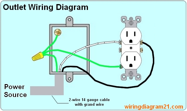
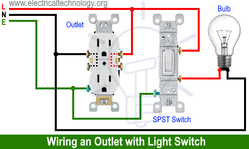
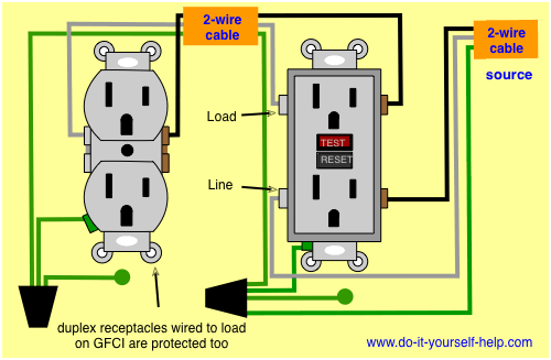
Wiring diagram for receptacle. Switched receptacle outlet wiring diagram depicting the electrical power feeding into an electrical receptacle box and then going to a switch and to another receptacle. In this case the circuit load flows both to the receptacle and to any downstream receptacles without being dependent on flowing through the receptacles connecting tab. Wiring a receptacle also referred to as an outlet is another of those fundamental wiring skills that every diyer should feel comfortable undertaking. In the diagram below a 2 wire nm cable supplies line voltage from the electrical panel to the first receptacle outlet box.
This repeats until the end of the chain. It shows the components of the circuit as streamlined shapes and the power as well as signal connections in between the devices. Higginbotham 20r wiring nema 6 20r nema 6 20 6 20p wiring nema 6 20r chart wiring a l6 20r outlet 6 20p wiring diagram 6 20p receptacle wiring wiring a nema 6 20r receptacle nema 6 20p wiring diagram. Steps to take when wiring the electrical outletreceptacle.
July 24 2018 april 12 2020 wiring diagram by anna r. The second method of wiring a mid run receptacle is to connect the receptacle to the circuit wires with pigtails that tap into the circuit wires passing through the box. A wiring diagram is a streamlined traditional photographic depiction of an electric circuit. These receptacles are usually found in kitchen wall outlets where two branch circuits are needed to serve small appliances and a refrigerator separately.
The black wire line and white neutral connect to the receptacle terminals and another 2 wire nm that travels to the next receptacle. Nema 6 20p receptacle wiring nema 6 20r wiring diagram. It reveals the parts of the circuit as simplified forms as well as the power and signal links in between the tools. Outlets are split wired so that the top half of the receptacle is live all of the time and the bottom of the receptacle is controlled by the wall switch.
Wiring diagram for a 20 amp 120 volt duplex receptacle a 20 amp 120v duplex receptacle outlet like this should be installed in a circuit using 12 awg cable and a 20 amp circuit breaker. Ordinary outlet or standard outlet has screws terminals on both sides. An outlet receptacle where one or more receptacle are installed or a supply contact device installed at the outlet to connect an electrical load through plugs and switches. This article and detailed wiring diagram explains the steps to wiring the common household receptacleoutlet.
Collection of ground fault receptacle wiring diagram.

An Electrician Explains How To Wire A Switched Half Hot Outlet
How To Wire An Outlet Receptacle Socket Outlet Wiring Diagrams
Wiring Diagrams For Electrical Receptacle Outlets Do It Yourself

How To Wire An Xlr Cannon Audio Plug How To Wire A Plug
Leviton Gfci Outlet Switch Combo Wiring Diagram Diagram Base

B3c912b Nema L14 20 Plug Wiring Diagram Wiring Library
Wiring Diagrams For Electrical Receptacle Outlets Do It Yourself

Thermostat Controlled Outlet 9 Steps With Pictures Instructables

Nema 6 30r Wiring Diagram Wiring Diagram
