Xlr To Jack Wiring Diagram
Xlr Cable Wiring Diagram Html
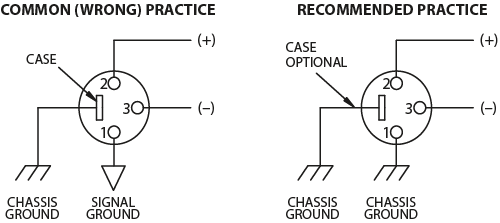
Rane Commercial Knowledge Base
Introduction For Pa System Assemblers
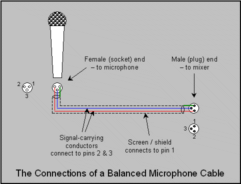
The above diagram shows you the pin numbering for both male and female xlr connectors from the front and the rear view.

Xlr to jack wiring diagram. Female 3 5mm jack wiring diagram this is a female xlr that plugs into a male microphone connection and a mm trs male connector at the other end to plug into a dslr stereo connection jack. Xlr to 14 trs connector wired for balanced mono the usual way to connect a 3 pin xlr to a 14 trs aka stereo jack plug is to use the following pin allocation. 3 5mm to xlr cable wiring diagram welcome to our site this is images about 3 5mm to xlr cable wiring diagram posted by benson fannie in 3 category on nov. Here is the essentials for soldering xlr and mic cables.
It reveals the components of the circuit as streamlined shapes and the power as well as signal links between the devices. This wiring configuration gives you a balanced mono audio cable. Xlr to 14 mono plug. The rear view is the end you solder from here are the connections on each pin.
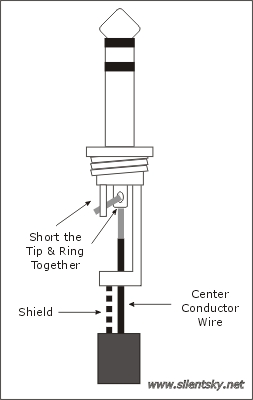
Xlr pin 2 to 14 plug tip. 3 pin xlr wiring standard. The most comon way to wire a 3 pin xlr to a 14 inch 65mm mono plug sometimes called a jack plug is to join the negative and shield together. 3 pin xlr wiring diagram cable wiring etc cable designed for being cut into standard mic cables may have 2 pairs of wire and a shield around the outside in that case pair the colors together and make sure they go to the same pin number on each end.
Xlr to 1 4 wiring diagram this is images about xlr to 1 4 wiring diagram posted by janell a. Note that an adapter designed for xlr to trs 14 will work in both a trs 14 jack and ts 14 jack. This can be done by either soldering the shield and negative wires of the xlr to the sleeve of the plug. Xlr pin 1 to 14 plug sleeve.
Any helpful comments. 3 pin xlr connectors are standard amongst line level and mic level audio applications. Xlr pin 3 to 14 plug ring. 35 mm jack to xlr wiring diagram wiring diagram is a simplified all right pictorial representation of an electrical circuitit shows the components of the circuit as simplified shapes and the faculty and signal connections between the devices.
A wiring diagram is a streamlined conventional photographic depiction of an electric circuit. Bueno in xlr category on nov 20 you can also find other images like wiring diagram parts diagram replacement parts electrical diagram repair manuals engine diagram engine scheme wiring harness fuse box vacuum diagram timing belt.

T1 Jack Wiring Diagram Diagram Base Website Wiring Diagram
Using An Insert Jack As A Direct Out Late Reflections The

Gotham Audio Llc Gotham Cables Gac 3 Neumann
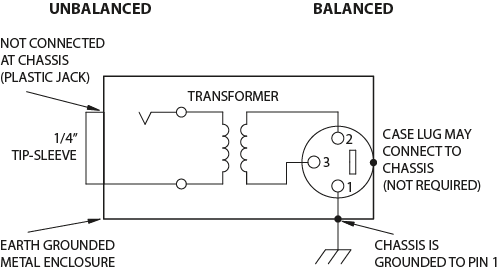
Rane Commercial Knowledge Base

5 Pin Xlr Stereo Wiring Diagram 4 Pin Xlr Intercom Wiring
Pc Microphone Phantom Powering Improvements

Wrg 7489 Xlr To 1 4 Wiring Diagram

Neutrik Xlr 1 4 Combo Jacks And Phantom Power Sound Design

Combo Xlr 1 4 Connectors
