Z Transform Transfer Function Block Diagram
Control Systems Quick Guide Tutorialspoint
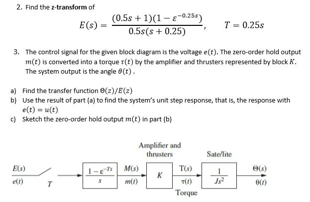
Solved 2 Find The Z Transform Of 0 5s 1 1 E 0 25s 0

Control Theory Wikipedia
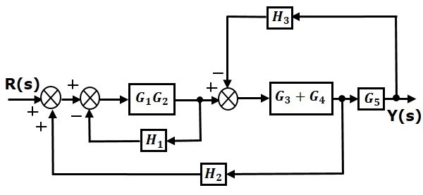
Second order system system algebra and block diagram.
Z transform transfer function block diagram. X z x n z n n notice that we include n 0 as well as n 0 bilateral z transform there is also a unilateral z transform with. A block diagram is a visualization of the control system which uses blocks to represent the transfer function and arrows which represent the various input and output signals. Transfer function block diagram confirmation. Z transform converts time domain operations such as difference and convolution into algebraic operations in z domain.
Yz hz uz. The conventional method for solving the above problem is the least squares solution method that is equal to the cross spectral method in stationary cases ie the system transfer function q w can be estimated by see eg. Hi this is a general question about z transform and block diagram. 36 videos play all digital control systems 2.
If the system transfer function is the z transform of the response to a suddenly applied sinusoid is let. H z h n z n. Then the system response can be written as and if the system is stable the steady state response is a dt sinusoid with generally different magnitude and phase. Block diagram algebra is introduced in section 23 as a suitable tool for obtaining transfer functions of systems whose block diagrams are known.
Although motivated by system functions we can dene a z trans form for any signal. For lecture material download from the link. Suppose yz is the output uz is the input and hz is the transfer function then. Considered in section 22.
The problem is to identify the lti system transfer function qw ie the fourier transform of qn given the input and the output signals xn and yn. Can someone confirm if this is the correct block diagram for the following transfer function. Moreover the behavior of complex systems composed of a set of interconnected lti systems can also be easily analyzed. The original equation provided was.
H n d z z z y n d cos cos z z z zz zz w w 0 2 0 21. The use of block diagram algebra to nd the system transfer function is advisable for simple systems but for complex systems it gets quite involved. A transfer function represents the relationship between the output signal of a control system and the input signal for all possible input values. The z transform and the pulse transfer function lutfi al sharif lecture 22 the z transform mit res6007 signals and systems spring 2011.
Newest z transform questions feed subscribe to rss newest z transform questions feed. In this lecture concept of block diagram representation for discrete time lti is discussed using z transform.
The Z Transform Xiii The Effect Of Sampling On The Z Transform Of
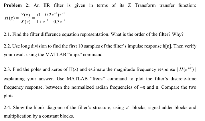
Problem 2 An Iir Filter S Given In Terms Of Its Z Chegg Com
Http Eceweb1 Rutgers Edu Gajic Solmanual Slides Chapter5 Bd Pdf
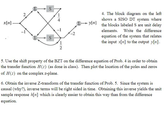
Solved X N 2 Yin 4 The Block Diagram On The Left Shows

Z Domain Simulation Fall 1996

5ei3 Modern Control Syste1

Z Transform Primer Ppt Download

Control Tutorials For Matlab And Simulink Introduction Pid
Continuous Discrete Conversion Methods Matlab Simulink
