Zoeller Well Pump Control Box Wiring Diagram
Zoeller P N006355 User S Manual Manualzz

Ex 7344 Wiring Diagram Likewise Zoeller Sump Pump Wiring Diagram

Wiring Diagram For Zoeller Pump
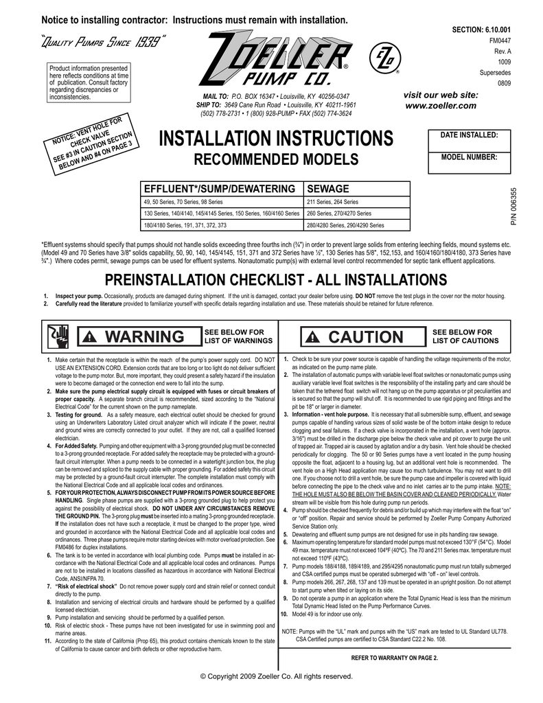
With one pump operating to handle normal flow a second pump becomes operational in the event the water level continues to rise.

Zoeller well pump control box wiring diagram. If it runs straight to the pressure switch it is a two wire. Here is the complete guide step by step. A defective wiring skip for 2 wire models check all motor and power line wiring in control box following the wiring diagram found inside box. This video shows wiring a franklin submersible pump control box.
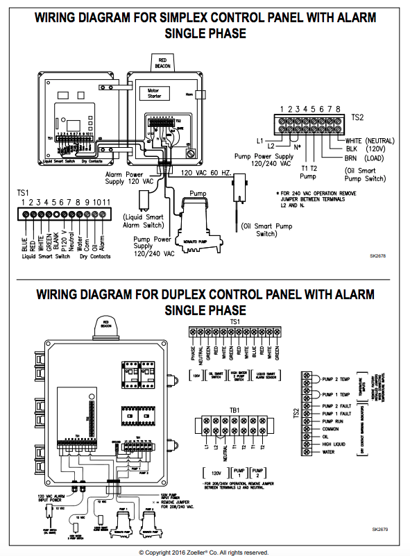
How to wire a submersible pump controller. A control box is required for 3 wire 230 volt submersible well pumps. Designed for outdoor applications. When the water tanks pressure switch detects low water pressure its switch closes which turns on the electricity to the control box.
Before getting started look up your owners manual and read over the precautions and all other warnings before beginning the installation. If the conduit runs into a control box before continuing to the water pressure switch chances are you have a three wire pump. Rewire any incorrect circuits. Well pump installation can be dangerous when dealing with water and electricity so extreme caution must be taken.
All 3 wire submersible pumps from 13 up to 1 hp utilize a qd control box to start the pump. In this video chris shows you how to wire the franklin electric qd control box. Technicians should test a well pumps control box before pulling a nonworking pump from the well. Once the water pressure reaches the switchs high pressure limit the switch opens turning off the electricity.
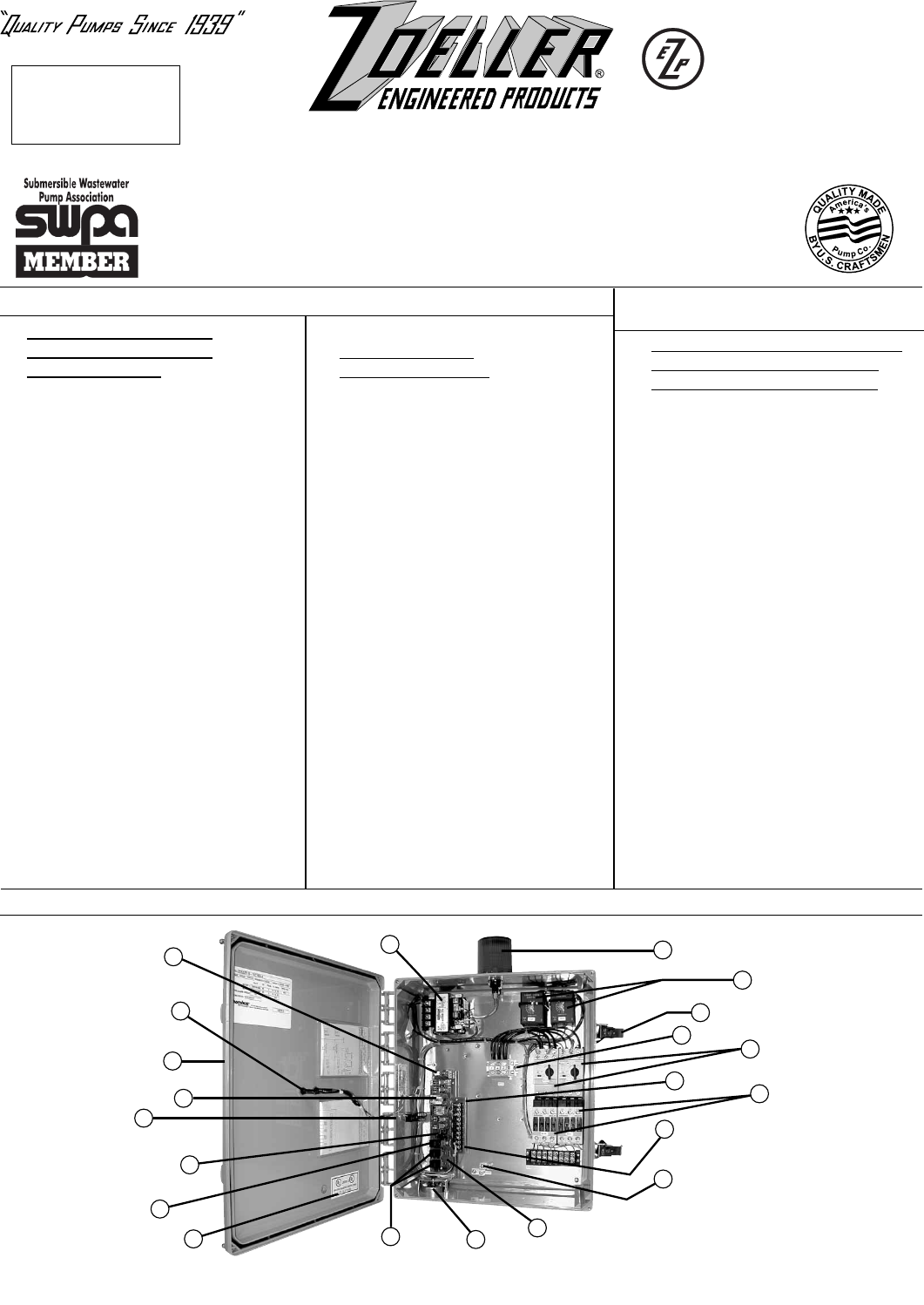
Zoeller pump company designs and manufactures pumps controls and accessories for sump effluent sewage and general dewatering applications. Single phase submersible pump control box wiring diagram 3 wire submersible pump wiring diagram in submersible pump control box we use a capacitor a resit able thermal overload and dpst switch double pole single throw. The wiring connection of submersible pump control box is very simple. A submersible pump can be either two or three wire regardless of the voltage coming from the panel so start at your pump and follow the conduit back.
Feature heavy duty terminal block for secure connections.

Zoeller Pump Switch Wiring Diagram Diagram Base Website Wiring

Fl 1743 Ejector Pump Control Box Wiring Diagram Download Diagram

Zoeller Automatic Submersible Sewage Pump 128 Gpm 1 2 Hp 25 Cord

Zoeller 10 2149 Oil Smart Simplex Control Panel 115v 1ph

Pump Accessories Parts Well Pump Control Box
17092 2 Zoeller Control Panel Diagram Zm1342 Panels User Manual

350f5 Zoeller Pump Switch Wiring Diagram Wiring Resources
Https Encrypted Tbn0 Gstatic Com Images Q Tbn 3aand9gcr Dqup0rae48v4zfd8u41tcdbdwkfgukctqb8gkcei4x8f1f1c Usqp Cau
Zoeller Oil Guard Systems Buyers Guide Review Pumpproducts Com
