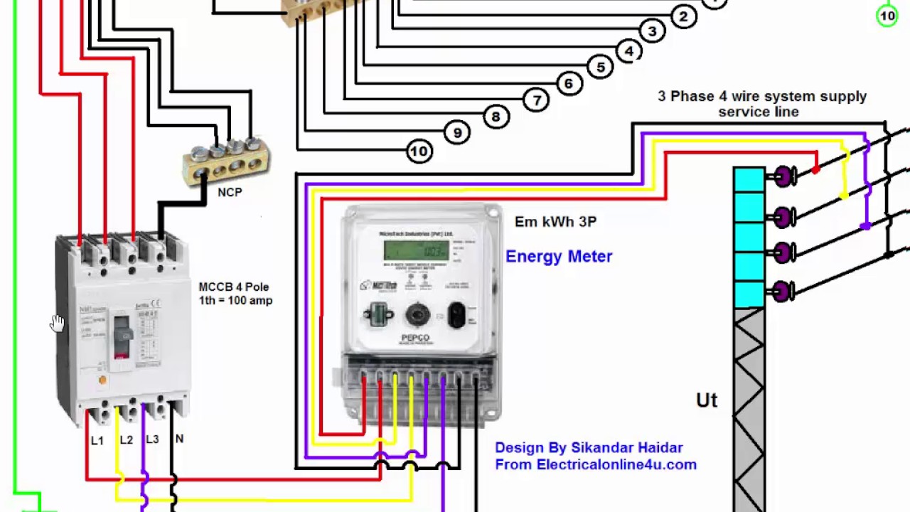
Rotary 3 Phase Converter Wiring Diagram
Rotary Static Digital Phase Converters Electrical Supply Napces
Baldor 3 Phase Wiring Diagram Free Picture Diagram Base Website
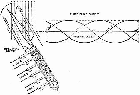
Three Phase Wikipedia
Always have phase converter on before starting any 3 phase load.

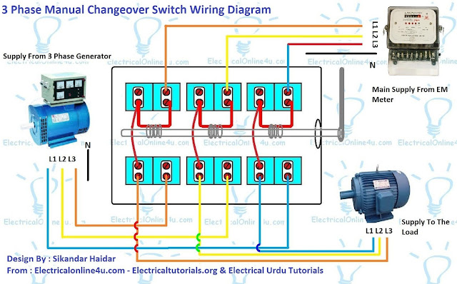
Rotary 3 phase converter wiring diagram. It shows the parts of the circuit as simplified forms and the power as well as signal connections in between the gadgets. Collection of rotary phase converter wiring diagram. Contactor c1 has replaced the drum switch and contactor c2 has replaced the momentary pushbutton for connecting the starting capacitor between l2 and l3. A wiring diagram is a simplified traditional pictorial representation of an electrical circuit.
A wiring diagram is a streamlined standard photographic depiction of an electric circuit. Assortment of rotary phase converter wiring diagram. Collection of american rotary phase converter wiring diagram. 1 phase to 3 phase rotary converter 230v to 415v duration.
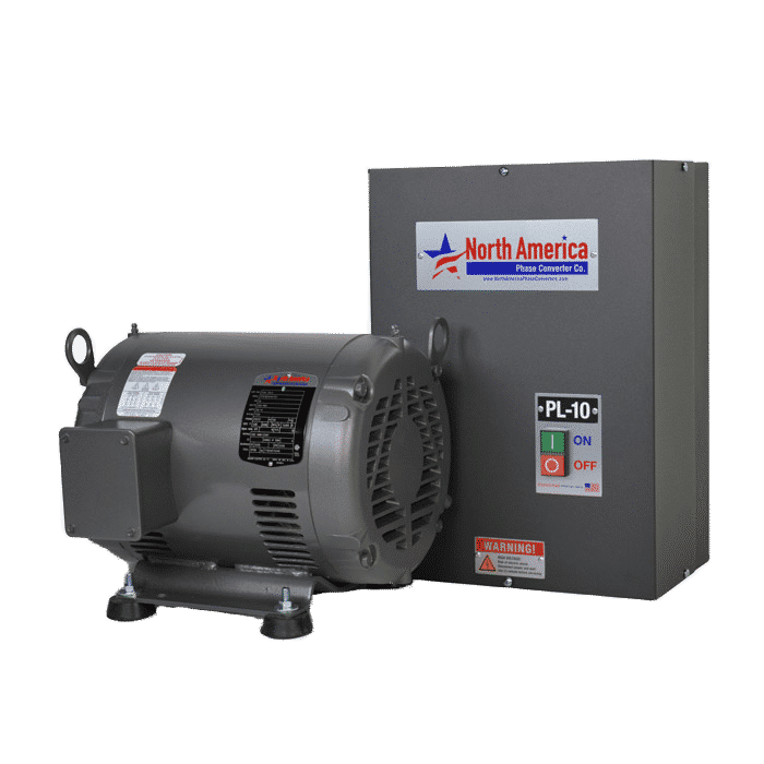
It reveals the elements of the circuit as simplified forms and the power and also signal links in between the gadgets. A wiring diagram is a simplified traditional photographic depiction of an electric circuit. Removable backplate large wiring compartment well marked oversized distribution blocks and conveniently located knockouts on all four sides of the control panel simplify installation of pro line rotary phase converters. Collection of 3 phase rotary converter wiring diagram.
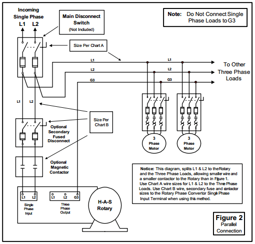
1 phase to 3 phase rotary converter 230v to 415v duration. It shows the elements of the circuit as simplified shapes and the power and also signal connections between the tools. Phase converter installation admin 2019 10 23t142252 0500 see how napcco design features make installation of pro line rotary phase converters easy. If you look closely you will see all the basic elements from the very simple static phase converter diagram shown earlier.
Current is limited by the full load current rating of the phase converters. All wiring must be done by a licensed electrician. Check phase alignment before adding additional phase converters to circuit. December 21 2017 at 1127 am.
It reveals the elements of the circuit as streamlined forms and also the power as well as signal connections between the devices. How to diy a three phase converter including the parts you need and information on how to connect the capacitor and relay. I need a power converter for my glass polisher the model the company suggest to use is a r5 by phase a matic i think your ar5 is the same can you tell me if you have the same converter as the r5 and how much it would cost. See page 5 for specs.
Wiring for my american rotary phase converter duration. A wiring diagram is a streamlined standard photographic depiction of an electrical circuit.
How To Install H A S Rotary Phase Conversion System

Practical Machinist Largest Manufacturing Technology Forum On

35 1 Phase To 3 Phase Converter Diagram Wiring Diagram List

Phase Converter Vs Vfds Which To Use Wolf Automation

8d15 Rotary Switch Spst Wiring Diagram Wiring Library

File Three Phase Voltage Source Inverter Circuit Schematic Jpg

1 Vs 3 Phase Contactors Contactors Overloads Product Guides
Baldor 3 Phase Wiring Diagram Free Picture Diagram Base Website
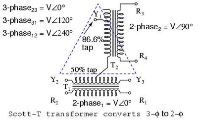
Scott T Transformer Wikipedia
