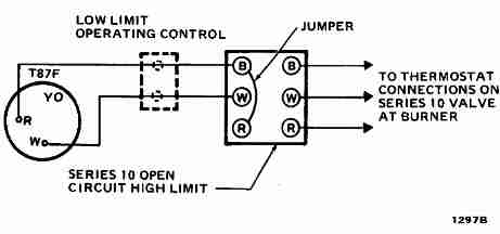
Typical Thermostat Wiring Diagram
If you have a two stage heat pump then you will also utilize terminal y2 for the second stage.

Typical thermostat wiring diagram. Honeywell thermostat wiring diagram 4 wire. Commonly used green white yellow and red thermostat wires. Furthermore this thermostat wiring diagram is specifically for a system with two transformers. Your system likely only has one transformer as most typical residential systems only use a single transformer for control.
The thermostat wiring on these systems can have very similar wiring properties. To wire a thermostat you must first be aware of the type of system that you have in your home. C is known as the common terminal. These two connections will ensure that there is power to the thermostat that you are operating.
This one uses the green wire as the c wire instead of the g fan wire. A remote temperature sensor is a solid state device. The color of wire r is usually red and c is black. A large majority of homes today have an hvac system containing a furnace oil gas or electric and an ac unit.
Finally this type of wire is different from the typical thermostat wire and a separate wire altogether. Furthermore the signal needed to get an accurate temperature is sensitive to electromagnetic forces from another wire inside the structure. As shown in the diagram you will need to power up the thermostat and the 24v ac power is connected to the r and c terminals. How to wire a thermostat.
That is a basic honeywell thermostat wiring diagram for a single stage heat pump.


