Pwm Schematic
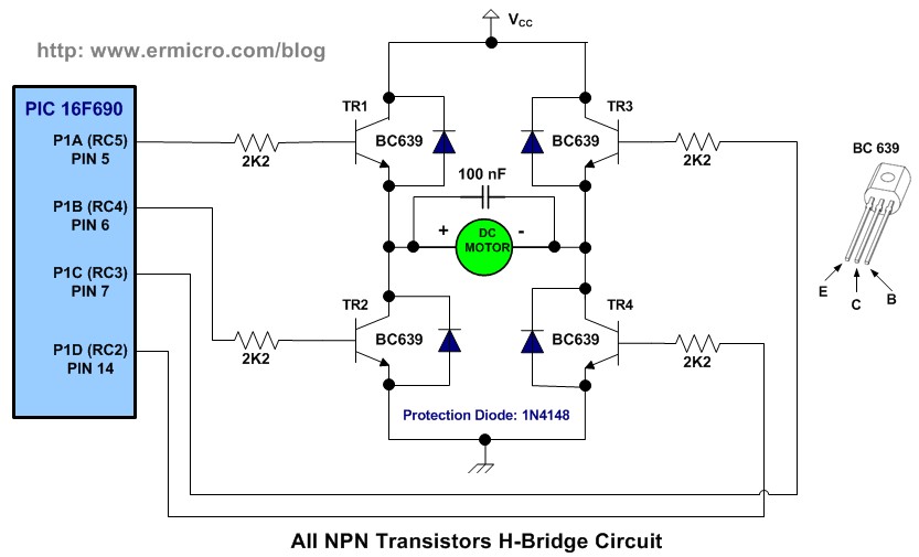
H Bridge Microchip Pic Microcontroller Pwm Motor Controller

Welcome To My Blog How To Make A Pwm Circuit Without A
16 Bit Audio Pwm By Dual 8 Bit Pwm With Auto Calibration Deeptronic
The output voltage adjustment is achieved with a pwm signal in this reference design at a frequency of 20 khz and a maximum clocking frequency of 10 mhz.
Pwm schematic. Thats what we seek to achieve here. Schematic for typical application tl5001a fb comp vo dtc rt vi scp vcc tps1101 gnd 8 7 6 5 2 1 3 4 vo. The pwm is a technique which is used to drive the inertial loads since a very long timethe simple example of an inertial load is a motor. Sometime we do not use microcontroller in our applications and if we need to generate pwm without microcontroller then we prefer some general purpose.
Pwm is widely used for motor controlling lighting controlling etc. Pwm is a technique used everywhere within electronics to vary the power supplied to devices and components such as motors leds and fans. Apply the power to a motor for a very short period of time and then turn off the power. The voltage can be adjusted with a pwm signal scaling an output voltage from 25 v through 43 v.
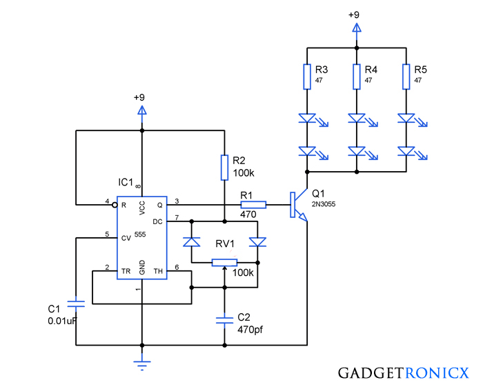
Pulse width modulation pwm allows for electronic control over dc motor speed or led brightness. Pwm pulse width modulation signal based inverters are produce output as pure sine wave and it can be used for any electric appliance that meets the inverter output range. Within this instructable the 555 timer is used to create a variable pwm signal that can be varied from 5 to 95 of the power supplied using a variable resistor. Pwm pulse width modulation is a important feature of todays every microcontroller due to its requirement for controlling many devices in every field of electronics almost.
Pulse width modulation control circuits. It can be observed that the motor is still running even after the power has been cut off from it. This articles features schematics and photos of circuits for making pwm without a microcontroller but instead uses a 74ac14 logic inverter chip diodes a capacitor and potentiometer. Which the pwmdtc comparator compares to the oscillator triangle wave as described in the previous section.
Pulse width modulation pwm put simply pwm is the process of switching power on and off to a device in pulses at a specific frequency. Same approach used in commercial light dimmers dc motor speed controller cpu fan speed controllers and etc. In this article i will show you how to create a ne555 timer ic based pwm dc motor speed controlleri will share the circuit diagram component list tips for making the circuit yourself and a fully working printable pcb layout.
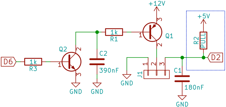
Pwm 3 Pin Pc Fan Schematic V2 Bald Engineer

Pwm Dc Power Controller

Simplest High Frequency Pwm With Ne555 5 Steps With Pictures

Discrete Pwm Generator Schematic Circuit Diagram

Schematic Structure Of A Voltage Pwm Inverter Download

Pwm Dac Settles In One Period Of The Pulse Train Edn Asia

A637149 Pwm Schematic Wiring Resources

Simplis Parts Trailing Edge Pwm

Schematics Com Search Results
